Protective device for baseplate of water conveyance canal at high groundwater table

A technology of protective devices and channels, applied in artificial waterways, water conservancy projects, buildings, etc., can solve the problems of siltation and blockage, increase head loss, improper protection measures, etc., to facilitate installation and demolition, increase head loss, and avoid blockage and damage. Effect

Active Publication Date: 2016-11-16
WATER RESOURCES RES INST OF SHANDONG PROVINCE
View PDF6 Cites 0 Cited by
  • Summary
  • Abstract
  • Description
  • Claims
  • Application Information

AI Technical Summary

Problems solved by technology

However, since the top elevation of the check valve installed at the bottom of the canal is generally 3-5cm higher than the floor elevation of the water delivery channel, the original design size and shape of the water delivery channel have been changed, coupled with improper protective measures and untimely daily maintenance, often The release of silt and blockage can not play its due role; at the same time, the check valve that is higher than the bottom plate of the water delivery channel also increases the head loss when the channel delivers water (head loss: the mechanical energy of the unit mass of liquid during the movement of the water flow The loss is called head loss; there are two reasons for head loss, internal and external, the external resistance to water flow is the main external cause of head loss, and the viscosity of liquid is the main internal cause and root cause of head loss), affecting water delivery capacity of the channel

Method used


Image

  • Protective device for baseplate of water conveyance canal at high groundwater table
  • Protective device for baseplate of water conveyance canal at high groundwater table
  • Protective device for baseplate of water conveyance canal at high groundwater table

Examples


Embodiment 1

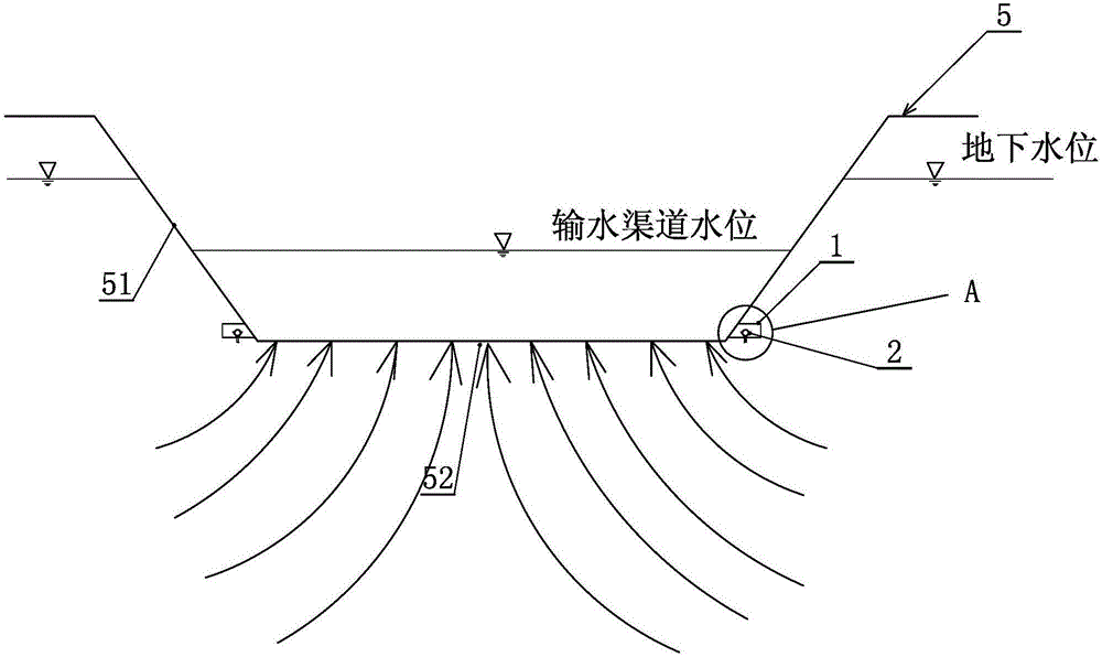
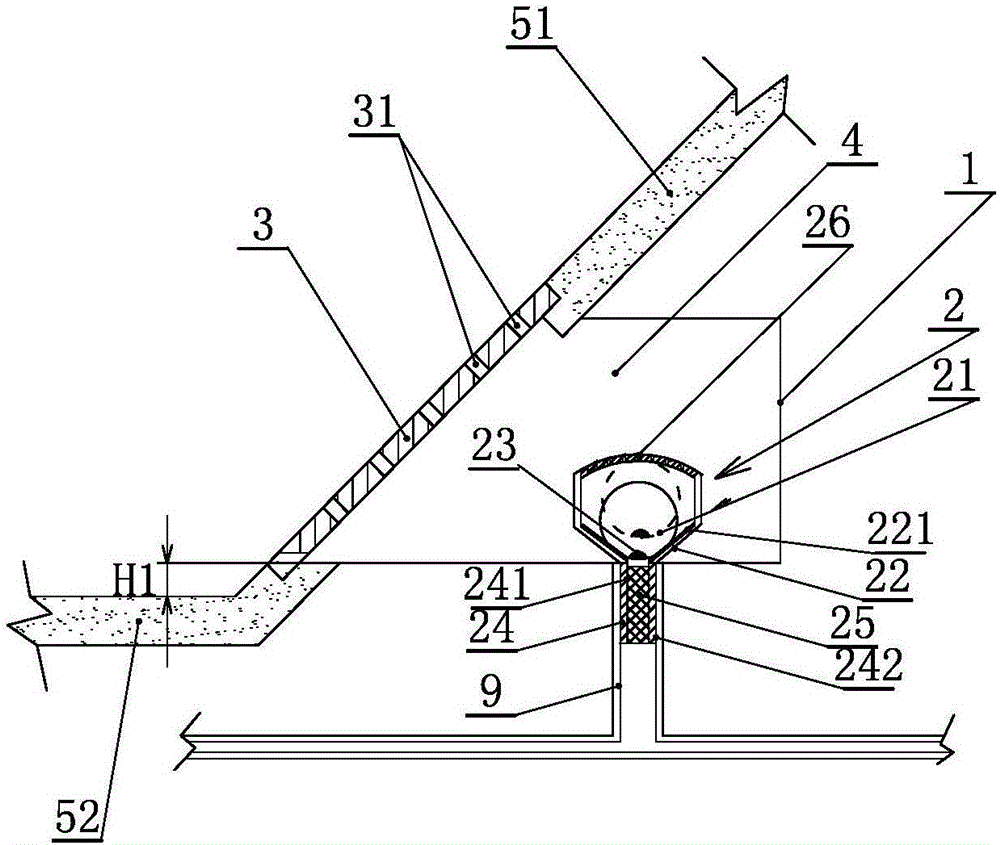
[0039] Embodiment one: if figure 2 , Figure 5 , Figure 12 and Figure 13 As shown, the protection device is composed of a housing 1, a one-way valve 2, a cover plate 3 and a pre-embedded vertical water pipe 9 and the like. The shell 1 is a reserved cavity shell with one end open and arranged at the bottom of the channel slope 51 on both sides of the water delivery channel 5, and its open end and the cover plate 3 can be fixed by bolts made of stainless alloy material connection; the cover plate 3 is a square plate, which is arranged obliquely at the bottom of the channel slope 51, and is fixed with the opening of the housing 1. A water storage chamber 4 is formed between the cover plate 3 and the housing 1. The size of the water storage chamber 4 can be determined according to Actual requirements design. A one-way valve 2 is installed in the water storage chamber 4, and when the uplift pressure generated by the groundwater is relatively large, the groundwater flows thro...

Embodiment 2

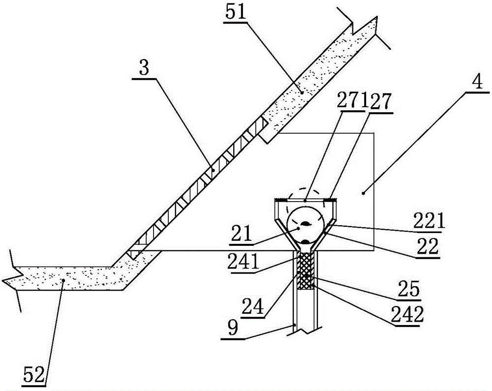
[0044] Embodiment two: if image 3 , Figure 14 As shown, the difference from Embodiment 1 is that the valve body of the check valve 2 has a conical opening 22, a valve core 21, and a vertical filter tube 24, and there is no raw material at the top of the circular section on the upper part of the conical opening 22. The rust alloy material bolt is fixedly connected to the limiting plate 27, the limiting plate 27 center is provided with a limiting hole 271, and the periphery is a water net 272 (such as Figure 14 As shown), when the one-way valve 2 is closed, the distance between the limit plate 27 and the height of the bottom of the conical mouth and the diameter of the limit hole 271 should be as high as the bottom elevation of the valve core 21 to the conical mouth 22 when the valve core 21 is fully opened. The height difference at the bottom is less than or equal to the radius of the spool 21 as the control basis. The setting of the limiting plate 27 has the same function...

Embodiment 3

[0045] Embodiment three: as Figure 4 As shown, the difference from Embodiment 1 and Embodiment 2 is that the valve body of the one-way valve 2 has a tapered mouth 22, a valve core 21, and a vertical filter pipe 24, and the inner top wall of the housing 1 is provided with There is a limit rod 28 that can be installed and disassembled. The bottom of the limit rod 28 is provided with a horn-shaped limit ring 281. The bottom of the limit ring 281 is facing the valve core 21. When the one-way valve 2 is closed, the The difference between the elevation of the limit ring 281 and the elevation of the top of the spool 21 is less than or equal to the radius of the spool 21 . The settings of the limiting rod 28 and the limiting ring 281 have the same effect as the setting of the limiting net 26, and will not be repeated here. The specific implementation process is that when the one-way valve 2 is fully opened, the spool 21 floats up, and is restricted by the limit ring 281 and stops to...


PUM

PropertyMeasurementUnit
Thicknessaaaaaaaaaa

Abstract

A protective device for a baseplate of a water conveyance canal at high groundwater table is fixedly arranged at the bottom of a water conveyance canal longitudinal slope and comprises a housing, a one-way valve and a cover plate, wherein the cover plate is fixedly arranged at the bottom of the water conveyance canal slope; water passing holes are formed in the cover plate; one end of the housing is open, and the open end is fixed with the cover plate; a water storage cavity is formed between the cover plate and the housing; the one-way valve is mounted in the water storage cavity, and underground water flows into the water storage cavity in one direction; and the difference between the elevations of the protective device and the base plate of the water conveyance canal is larger than zero. After the protective device is arranged at the bottom of the water conveyance canal slope, the effect of automatic closure without increasing water head loss during water conveyance is achieved; and the one-way valve is automatically opened when the groundwater table is higher than the water level of the canal, so that uplift pressure, caused by high groundwater table, on the baseplate of the canal is reduced.

Description

technical field [0001] The invention relates to the technical field of water conservancy and hydropower engineering, and relates to a protective device for the bottom plate of a water delivery channel in a high groundwater level area. Background technique [0002] For water delivery channels in areas with high groundwater levels, the floor concrete often breaks after water delivery. One of the reasons is that the groundwater level is higher than the elevation of the water delivery channel (elevation refers to the absolute The distance from the base surface is called the absolute elevation, referred to as the elevation. The distance from a certain point along the vertical line to a certain hypothetical level base is called the hypothetical elevation). Structural damage occurred. [0003] The existing technical measures have taken the addition of a check valve on the bottom of the channel, which can introduce the groundwater with a higher water level near the bottom of the wa...

Claims


Application Information

Patent Timeline
IPC IPC(8): E02B5/02E02B5/08
CPCE02B5/02E02B5/08
Inventor 贾翠兰刘冠麟田志刚徐运海王玉太魏兆珍刘莉莉刘云张立华程素珍安凯军巩向峰郝晓辉王光辉杨大伟
Owner WATER RESOURCES RES INST OF SHANDONG PROVINCE
Why Eureka
Try Eureka