
Hydraulic mineral collecting head of submarine mining vehicle and mineral collecting method

A mining vehicle and hydraulic technology, which is applied to the hydraulic ore collecting head and its ore collecting field, can solve the problems of high energy consumption, ecological damage to the seabed, and large impact on the deep sea ecology.

Active Publication Date: 2016-11-16
SHANGHAI JIAO TONG UNIV
View PDF6 Cites 2 Cited by
  • Summary
  • Abstract
  • Description
  • Claims
  • Application Information

AI Technical Summary

Problems solved by technology

Due to the deep-sea terrain, deep-sea power, deep-sea communication, etc., the working range and working efficiency of this method are severely limited; the second is floating mining, which uses high-speed jetting water to blow up the seabed ore, and uses hydraulic or pneumatic power through pumps and pipelines. The ore is lifted from the seabed by means of this method, which is less affected by the deep sea environment, but consumes a lot of energy, and there is a lot of mud in the collected ore, which has a greater impact on the deep sea ecology
[0005] In summary, in order to improve the low production efficiency, high energy consumption, and serious damage to seabed ecology of the original seabed mining equipment, the present invention proposes a hydraulic ore collection head for a seabed mining vehicle and a method for collecting ore

Method used


Image

  • Hydraulic mineral collecting head of submarine mining vehicle and mineral collecting method
  • Hydraulic mineral collecting head of submarine mining vehicle and mineral collecting method
  • Hydraulic mineral collecting head of submarine mining vehicle and mineral collecting method

Examples


Embodiment Construction

[0028] The specific embodiments of the present invention are given below in conjunction with the accompanying drawings, but the present invention is not limited to the following embodiments. Advantages and features of the present invention will be apparent from the following description and claims. It should be noted that all the drawings are in very simplified form and use imprecise ratios, which are only used for the purpose of conveniently and clearly assisting in describing the embodiments of the present invention.

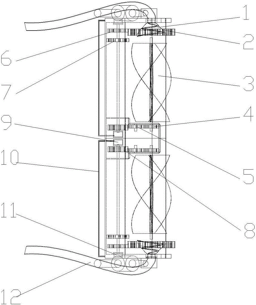
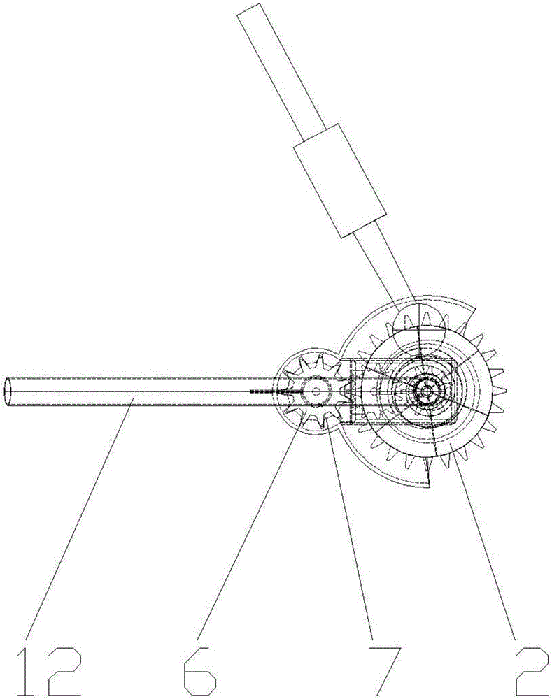
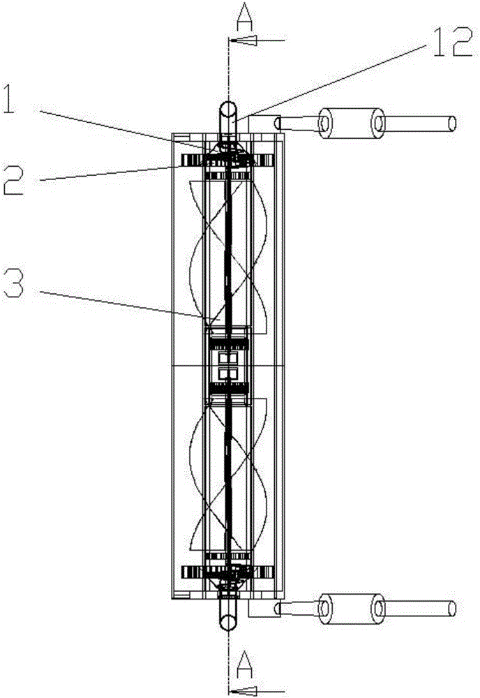
[0029] Please refer to Figure 1 ~ Figure 4 , figure 1 Shown is a schematic structural diagram of the hydraulic collecting head of the seabed mining vehicle in a preferred embodiment of the present invention. figure 2 Shown is a schematic diagram of the cooperation structure of the dial-type height-limiting wheel and the transmission gear set in a preferred embodiment of the present invention. image 3 Shown is a schematic diagram of the structure of the h...


PUM


Abstract

The invention provides a hydraulic mineral collecting head of a submarine mining vehicle and a mineral collecting method. The hydraulic mineral collecting head comprises a shell with an opening, mineral conveying pipes, support connectors and spiral rotating plates, wherein the support connectors and the mineral conveying pipes are connected to the outer side of the shell, and the spiral rotating plates are arranged in the shell. Spiral mineral sucking covers are arranged at the two sides in the shell, cylindrical parts at the bottom ends of the spiral mineral sucking covers are connected with the mineral conveying pipes by bearings, the front ends of the spiral mineral sucking covers are fixedly connected with driving plate type height limiting wheels, the driving plate type height limiting wheels and a driving gear group are matched with each other and are all arranged on the side, far from the opening, of the shell, the two ends of a shaft of the driving gear group separately extend into a first hydraulic cabin and a second hydraulic cabin, and the two hydraulic cabins communicate via a conveying pipe. The collection of submarine minerals is realized by adopting spiral water flow, and external gear shifting can be realized when running speed does not meet requirements. Compared with original submarine mineral collecting equipment, the hydraulic mineral collecting head is more environment-friendly, efficient, energy-saving and reliable.

Description

technical field [0001] The invention relates to the technical field of mining resource equipment, in particular to a hydraulic ore collecting head of a seabed mining vehicle and a method for collecting ore. Background technique [0002] With the rapid development of the world's industry and economy, the consumption of mineral resources has increased sharply, and land mineral resources are becoming increasingly scarce or even exhausted on a global scale. Human beings have turned their attention to the ocean, which accounts for 71% of the earth's surface area. The exploitation of marine mineral resources is to make up for the depletion of land resources. effective way. [0003] In the international seabed area, there are rich metal mineral resources such as manganese nodules, cobalt-rich crusts, thermal sulfides and polymetallic oozes. Due to the differences in the seabed environment of various resources and changes in the ancient ocean, the distribution of each mineral is dif...

Claims


Application Information

Patent Timeline
IPC IPC(8): E21C50/00B63C11/52
CPCB63C11/52E21C50/00
Inventor 肖龙飞赵国成陈芝燚寇雨丰田新亮胡经朝宋春辉邓博贤
Owner SHANGHAI JIAO TONG UNIV
Learn More