Intelligent ventilation monitoring system based on tunnel environment

A monitoring system and tunnel environment technology, which is applied in mine/tunnel ventilation, mining equipment, mining equipment, etc. It can solve the problems of no monitoring system, economic loss, and inability to timely lock dangerous positions, etc., and achieves simple structure and convenient use Effect

Inactive Publication Date: 2016-11-16
CHENGDU SYSWARE ELECTRONICS INFORMATION
View PDF4 Cites 9 Cited by
  • Summary
  • Abstract
  • Description
  • Claims
  • Application Information

AI Technical Summary

Problems solved by technology

[0003] However, most of the current tunnel ventilation systems do not have a monitoring system. The ventilation system is c...

Method used


Image

  • Intelligent ventilation monitoring system based on tunnel environment

Examples


Embodiment 1

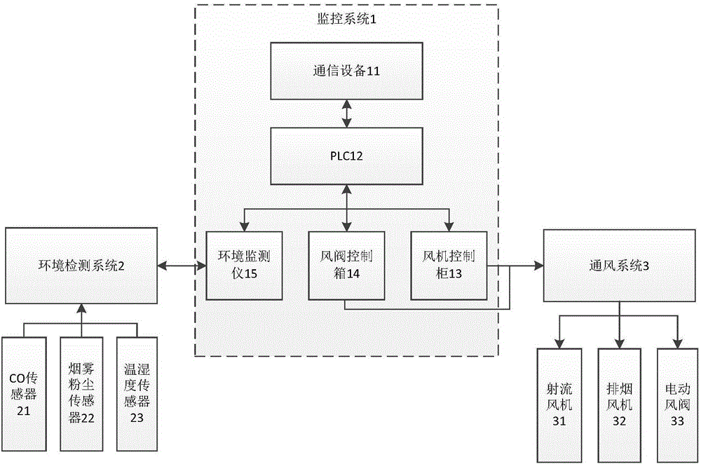
[0013] Embodiment 1: Under normal circumstances, according to the environmental parameters such as CO, dust that environmental detection system 2 collects, one or several jet fans 31 are automatically turned on and off by PLC12; according to the tunnel wind direction, the jet fans 31 are controlled to rotate forward and Reversed, to inhale fresh air into the tunnel, and at the same time, according to the working hours of the jet fans 31, the jet fans 31 are automatically controlled to start and stop in turn, so as to be used repeatedly, so as to avoid one or more jet fans 31 from starting and stopping too frequently, which may cause the jet fans 31 to fail. The service life is shortened; when the train passes through the tunnel or stops in the tunnel, the ventilation system 3 is automatically opened, and when the train leaves the tunnel, the ventilation system 3 is automatically closed to save electric energy.

Embodiment 2

[0014] Embodiment 2: When a fire occurs, PLC12 controls all the exhaust fans 32 to perform smoke exhaust work, and the smoke exhaust direction is along the direction of the tunnel; for extra-long tunnels, it is controlled according to the predetermined disaster plan; all jet fans 31 are turned on during the fire extinguishing stage And smoke exhaust fan 32, increase air volume, to be beneficial to extinguishing a fire, cooling and smoke exhaust. After the fire extinguishing, the fan is gradually turned off by the PLC12 or the on-site control cabinet. After confirming that it can pass normally, the original setting of various equipment operating states will be restored.

Embodiment 3

[0015] Embodiment 3: When a certain equipment of the ventilation system 3 breaks down and cannot continue to operate, the PLC12 will automatically switch to the standby equipment, and at the same time send an alarm signal to notify the maintenance personnel to detect, in order to prevent a wider range of equipment failures.


PUM


Abstract

The invention discloses an intelligent ventilation monitoring system based on a tunnel environment. The ventilation monitoring system comprises a monitoring system body, an environmental detection system and a ventilation system, wherein the monitoring system body comprises communication equipment, a PLC, a fan control cabinet, an air valve control box and an environment monitoring instrument; the communication equipment is connected with the PLC; the PLC is separately connected with the fan control cabinet, the air valve control box and the environment monitoring instrument; the fan control cabinet and the air valve control box are connected with the ventilation system; and the environment monitoring instrument is connected with the environmental detection system. According to the intelligent ventilation monitoring system disclosed by the invention, the ventilation system in the tunnel and the environmental detection system are intelligently monitored by the monitoring system, whether the working of the ventilation system in the tunnel is normal or not can be monitored in real time, and different ventilation equipment is adopted according to data monitored by the environmental detection system. The intelligent ventilation monitoring system disclosed by the invention is simple in structure and convenient to use.

Description

technical field [0001] The invention relates to the technical field of tunnel ventilation, in particular to an intelligent ventilation monitoring system based on a tunnel environment. Background technique [0002] The function of tunnel ventilation is to deliver enough fresh air from the outside of the tunnel to the inside of the tunnel and discharge the harmful gas in the tunnel to ensure the normal operation of the tunnel. During the operation of the train, smoke and harmful gases will be generated. The quality of the tunnel ventilation system will affect directly affect driving safety. [0003] However, most of the current tunnel ventilation systems do not have a monitoring system. The ventilation system is completely inspected manually, and the location of the dangerous situation cannot be locked in time, thus causing economic losses. Contents of the invention [0004] In order to solve the above problems, the object of the present invention is to provide a monitoring...

Claims


Application Information

Patent Timeline
IPC IPC(8): E21F17/18E21F1/00E21F1/08
CPCE21F1/003E21F1/08E21F17/18
Inventor 翟纯玉张军陈伟
Owner CHENGDU SYSWARE ELECTRONICS INFORMATION
Why Eureka
Try Eureka