
Control concept for closed loop brayton cycle

A technology for working fluids and turbines, applied in parts of pumping devices for elastic fluids, engine control, jet propulsion devices, etc., can solve problems such as rotor rupture, danger, and slowness

Active Publication Date: 2016-11-16
GENERAL ELECTRIC TECH GMBH
View PDF4 Cites 4 Cited by
  • Summary
  • Abstract
  • Description
  • Claims
  • Application Information

AI Technical Summary

Problems solved by technology

But because the storage system 9 reduces the turbine 2 torque too slowly, as a result, the balance between the driving torque from the turbine 2 and the resistance torque from the generator 7 is positive, i.e. the shafting 3 will accelerate and its rotational speed will raise dangerously, which could crack the rotor if care is not taken

Method used


Image

  • Control concept for closed loop brayton cycle
  • Control concept for closed loop brayton cycle
  • Control concept for closed loop brayton cycle

Examples


Embodiment Construction

[0050] For a thorough understanding of the present invention, reference is made to the following detailed description including the appended claims taken in conjunction with the accompanying drawings. In the following description, for purposes of explanation, numerous specific details are set forth in order to provide a thorough understanding of the present invention. It will be apparent, however, to one skilled in the art that the present disclosure may be practiced without these specific details. In other instances, structures and devices are shown in block diagram form only in order to avoid obscuring the invention. References in this specification to "one embodiment," "another embodiment," "another embodiment," and "various embodiments" mean that a particular feature, structure, or characteristic described in connection with the embodiments is included in at least one aspect of the present disclosure. In one embodiment. The appearances of the phrase "in one embodiment," ...


PUM


Abstract

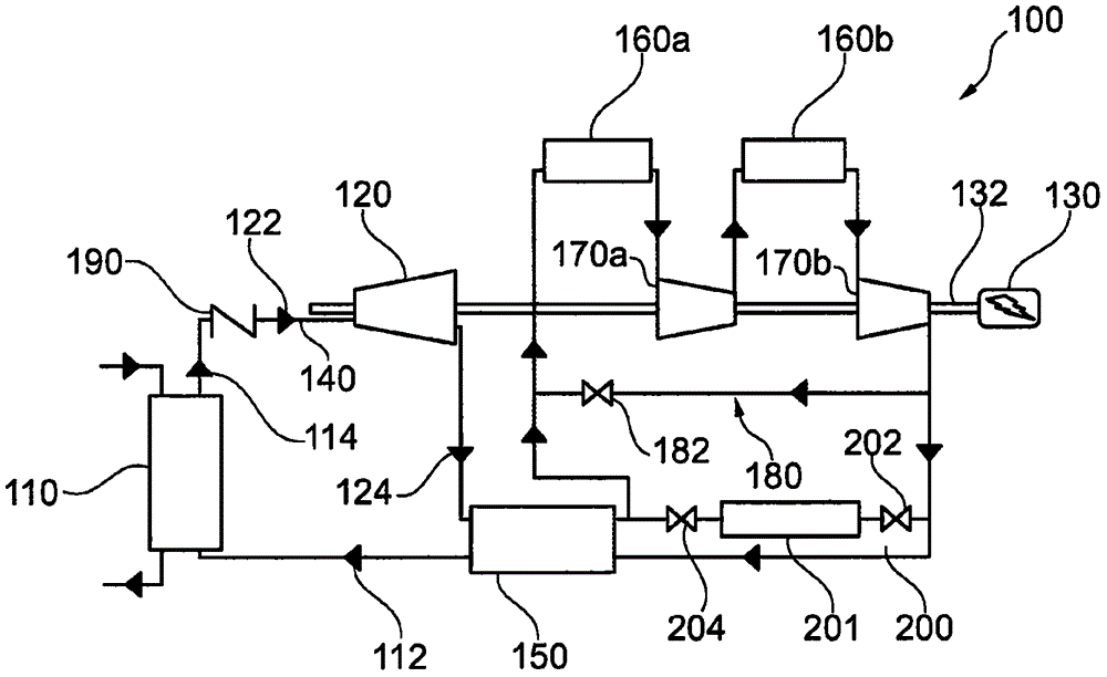
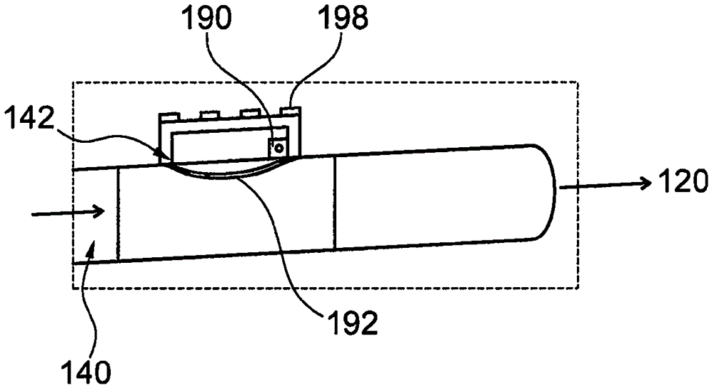
The invention relates to a control concept for a closed loop brayton cycle. The improved closed loop Brayton cycle 100 for a power plant is provided that includes a heater 110, at least one turbine 120, a recuperator 150, at least one cooler 160, at least one compressor 170, a bypass line 180 and a flap valve arrangement 190 in a closed circuit in which working fluid is circulated to produce electricity via a generator 132. Depending upon the requirement, such as, in case of gird load disconnection, speed of a shaft-line to which the turbine 120, the compressor 170 and the generator 132 are configured is also required to be reduced without any impact on the pressure drop in the cycle. For that the non-tight flap valve arrangement 190 is configured on each conduit 140 between the heater 110 and the at least one turbine 120 in a closest possible proximity to each turbine inlet 122.

Description

technical field [0001] The present disclosure relates generally to closed-loop Brayton cycles, and more particularly to improved control concepts for closed-loop Brayton cycles, with the specific aim of controlling airflow in such cycles during generator disconnection from the grid. advantage. Background technique [0002] It is well known that the working fluid for converting heat into electricity in a closed Brayton cycle power plant is a gas. [0003] In one such known closed Brayton cycle power plant cycle 10, as figure 1 As shown in the prior art of , comprising at least one compressor 1 and turbine 2 on a shaft 3, a cooler 4, a recuperator 5 and a heater 6 are arranged in a closed loop cycle to operate and via a generator 7 (which Also configured on shaft 3) to generate electricity for transmission to the grid. This cycle also includes a bypass control arrangement 8 near the compressor, and a storage system 9 arranged in the cycle 10 . However, the efficiency of cy...

Claims


Application Information

Patent Timeline
Patent Type & Authority Applications(China)
IPC IPC(8): F01K25/00F01D17/10
CPCF01D17/105F01K25/00F05D2270/3061F01D17/145F01D17/148F02C1/105F02C9/20F05D2270/304F05D2270/021F05D2260/606F05D2270/091F01K21/00F02G2250/03F01K5/00F01D5/02F02C9/16F04D29/321F05D2260/20
Inventor P·拉夫方特
Owner GENERAL ELECTRIC TECH GMBH
Learn More