Vacuum pump electronic controller

An electronic controller and vacuum pump technology, applied in pump control, pumps, machines/engines, etc., can solve problems such as unreliable braking of automobiles, affecting the normal operation of vacuum boosters, and falling off of vacuum pumps

Active Publication Date: 2016-11-16
华景传感科技(无锡)有限公司
View PDF10 Cites 6 Cited by
  • Summary
  • Abstract
  • Description
  • Claims
  • Application Information

AI Technical Summary

Problems solved by technology

However, since the vacuum pumps used in automotive vacuum boosters are usually installed and fixed by threaded fasteners, affected by the bumps and vibrations during the operation of the car, onc...

Method used


Image

  • Vacuum pump electronic controller

Examples


Embodiment

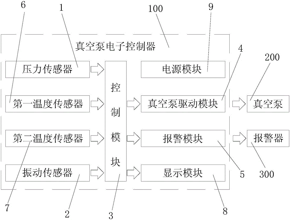
[0020] figure 1 It is a structural block diagram of the vacuum pump electronic controller provided by the embodiment of the present invention. Such as figure 1 As shown, this embodiment provides a vacuum pump electronic controller 100 , the vacuum pump electronic controller 100 includes: a pressure sensor 1 , a vibration sensor 2 , a control module 3 , a vacuum pump driving module 4 and an alarm module 5 .

[0021] Specifically, the control module 3 is electrically connected to the pressure sensor 1 and the vibration sensor 2 respectively, and the vacuum pump driving module 4 bridges the control module 3 and the driving motor of the vacuum pump 200, and the vacuum pump driving module 4 has the ability to withstand large currents. When the vacuum pump 200 is short-circuited by the driving motor or generates a large current at the moment of starting, the vacuum pump driving module 4 can independently withstand the large current to protect the control module 3 from being damaged...


PUM


Abstract

The invention discloses a vacuum pump electronic controller, which comprises a pressure sensor used for detecting the air pressure in a vacuum tank in real time and outputting a corresponding air pressure actual value, a vibration sensor used for detecting the vibration amplitude of a vacuum pump in real time and outputting a corresponding vibration actual value, a control module electrically connected with the pressure sensor and the vibration sensor, a vacuum pump drive module bridged with a control module and a drive motor of the vacuum pump, and an alarm module electrically connected with the control module. The vacuum pump electronic controller stabilizes an air pressure value in the vacuum tank. In addition, a driver or passengers in a car can be reminded to find the vibration problem of the vacuum pump through an alarm manner, so that the braking safety and the reliability of a vacuum booster are ensured.

Description

technical field [0001] The invention relates to the technical field of vacuum pump controllers, in particular to a vacuum pump electronic controller. Background technique [0002] A vacuum booster is generally designed in the braking mechanism of an electric vehicle. The vacuum booster is a vacuum pump that lowers the external air pressure under the control of the controller. force. The vacuum pump controller realizes the start-stop control of the vacuum pump according to different working states. [0003] For example, the Chinese utility model patent (CN205113316U) discloses a vacuum pump controller for electric vehicles, which includes: a vacuum pressure sensor circuit, a single-chip microcomputer circuit, a power processing circuit, an electronic vacuum pump drive circuit, an electronic vacuum pump operating current detection circuit, Abnormal alarm circuit; the vacuum pressure sensor circuit obtains the pressure value inside the vacuum booster. When the pressure value ...

Claims


Application Information

Patent Timeline
IPC IPC(8): F04B49/06F04B49/10F04B37/14
CPCF04B37/14F04B49/06F04B49/10
Inventor 缪建民鞠香陈欣悦
Owner 华景传感科技(无锡)有限公司
Why Eureka
Try Eureka