
Indoor harmful gas removing device based on low-temperature cold source

A low-temperature cold source, harmful gas technology, used in indoor harmful gas removal devices, harmful gas purification fields, can solve the problems of limited purification effect, secondary pollution, etc., to achieve safe discharge, convenient secondary pollution, and no secondary pollution. The effect of pollution

Inactive Publication Date: 2016-11-16
CSIC PRIDE (NANJING) CRYOGENIC TECHNOLOGY CO LTD
View PDF4 Cites 5 Cited by
  • Summary
  • Abstract
  • Description
  • Claims
  • Application Information

AI Technical Summary

Problems solved by technology

But the disadvantage is that all kinds of filters need to be replaced regularly due to adsorption saturation, and secondary pollution is easily generated after saturation. At the same time, the adsorption performance of the filters is affected by the water vapor in the air and the adsorbent itself, and the actual purification effect is limited.

Method used


Image

  • Indoor harmful gas removing device based on low-temperature cold source
  • Indoor harmful gas removing device based on low-temperature cold source

Examples


Embodiment 1

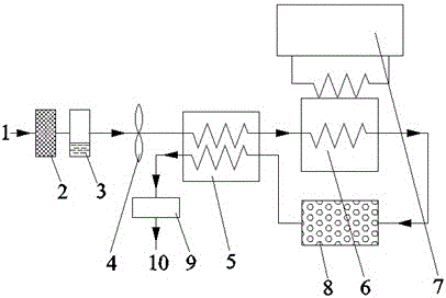
[0024] Such as figure 1 As shown, an indoor harmful gas removal device based on a low-temperature cold source includes a primary heat exchanger 5, a secondary heat exchanger 6, an adsorber 8, a low-temperature cold source 7, an air inlet 1 and a primary heat exchanger 5 The gas inlet of the primary heat exchanger 5 is connected with the gas inlet of the secondary heat exchanger 6, and the gas outlet of the secondary heat exchanger 6 is connected with the gas inlet of the primary adsorber 8. The gas outlet of the primary adsorber 8 is connected to the cold end inlet of the primary heat exchanger 5, the cold end outlet of the primary heat exchanger 5 is connected to the air outlet 10, and the low-temperature cold source 7 is connected to the secondary heat exchanger 6 phase connection.

[0025] Between the air inlet 1 and the primary heat exchanger 5, a filter screen 2, a dehumidification device 3, and a fan 4 are sequentially arranged, and a humidifier 9 is arranged between th...

Embodiment 2

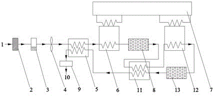
[0029] In order to obtain air with a higher degree of cleanliness, this embodiment adopts a combination of multi-stage heat exchangers and adsorbers.

[0030] In this embodiment, the first-stage heat exchanger 5 and the third-stage heat exchanger 11 adopt plate-fin heat exchangers, the second-stage heat exchanger 6 and the fourth-stage heat exchanger 12 adopt finned heat exchangers, and the first-stage adsorber The adsorbent used in 8 is molecular sieve, the adsorbent used in the secondary adsorber 13 is activated carbon, and the low-temperature cold source 7 is a refrigerator.

[0031] Such as figure 2 As shown, the secondary heat exchanger 6 and the fourth-stage heat exchanger 12 of an indoor harmful gas removal device based on a low-temperature cold source are connected to the low-temperature cold source 7 respectively, and the air inlet 1 is connected to the gas of the primary heat exchanger 5 The inlets are connected, the gas outlet of the primary heat exchanger 5 is co...


PUM


Abstract

The invention discloses an indoor harmful gas removing device based on a low-temperature cold source. The indoor harmful gas removing device based on the low-temperature cold source comprises a loop formed by a heat exchanger, an adsorber and the low-temperature cold source, and further comprises an air pipeline, wherein an air inlet of the air pipeline is connected with a gas inlet of the heat exchanger; and a cold end outlet of the heat exchanger is connected with an air outlet of the air pipeline. Condensation or freezing temperatures of various harmful foreign gases in air are different, the various harmful foreign gases are condensed, frozen or adsorbed at low temperature in the heat exchanger and the adsorber, so that harmful gases such as formaldehyde, nitrogen oxide and volatile organic compounds in the indoor air are removed, and the purpose of purifying the air is achieved. In a regeneration process of the device, the gases are discharged safely, conveniently and fast, and secondary pollution cannot be caused.

Description

technical field [0001] The invention relates to the technical field of harmful gas purification, in particular to the technical field of an indoor harmful gas removal device based on a low-temperature cold source. Background technique [0002] From the analysis of indoor air quality in my country, the main sources of indoor air pollutants are building and interior decoration materials, outdoor pollutants, combustion products and human activities. Among them, the pollution of interior decoration materials and furniture is the main aspect that causes indoor air pollution, such as formaldehyde, toluene, ammonia, VOCs, etc., and a very small amount can cause great harm to human health. [0003] In daily life, people can use low-cost methods such as displacement ventilation, placing green plants or activated carbon in the home environment to remove harmful gases, but they can only be used as an inefficient auxiliary measure. In comparison, professional air purifiers are more wid...

Claims


Application Information

Patent Timeline
Patent Type & Authority Applications(China)
IPC IPC(8): F24F1/00F24F3/16F24F13/28F24F13/30
CPCF24F1/00F24F3/14F24F3/16F24F13/28F24F13/30F24F1/0071F24F8/10F24F8/108F24F8/15F24F8/158
Inventor 陈杰段罗斌高金林刘茂农丁晗飞
Owner CSIC PRIDE (NANJING) CRYOGENIC TECHNOLOGY CO LTD
Learn More