
Micro-channel heat pump loop provided with gas-liquid separation devices arranged in front of evaporators

The technology of a gas-liquid separation device and a micro-channel heat exchanger, which is applied in the field of heat pumps, can solve the problems of reduced system efficiency and uneven distribution, and achieves the effect of ensuring the heat exchange effect and improving the heat exchange efficiency.

Active Publication Date: 2016-11-16
浙江豪瓦特节能科技有限公司
View PDF4 Cites 2 Cited by
  • Summary
  • Abstract
  • Description
  • Claims
  • Application Information

AI Technical Summary

Problems solved by technology

[0002] At present, microchannel heat exchangers are widely used in automotive air conditioners, commercial air conditioners, computer room air conditioners and other fields, mainly as condensers. When traditional microchannel heat exchangers are used as heat pump system evaporators, due to the refrigerant in each flat tube The density of the gas-liquid two-phase refrigerant in the microchannel is different, resulting in very uneven distribution. The phenomenon of "dry evaporation" and "excessive liquid supply" are very common among the microchannels of the flat tubes of the heat exchanger, and the uneven distribution of the refrigerant Uniformity has a great impact on the performance of the system, which greatly reduces the efficiency of the system

Method used


Image

  • Micro-channel heat pump loop provided with gas-liquid separation devices arranged in front of evaporators
  • Micro-channel heat pump loop provided with gas-liquid separation devices arranged in front of evaporators
  • Micro-channel heat pump loop provided with gas-liquid separation devices arranged in front of evaporators

Examples


Embodiment Construction

[0040] The present invention will be described in further detail below in conjunction with the accompanying drawings and specific embodiments.

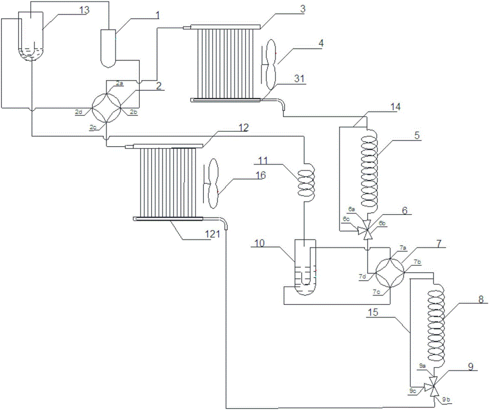
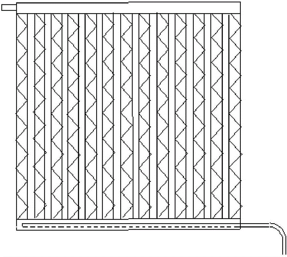
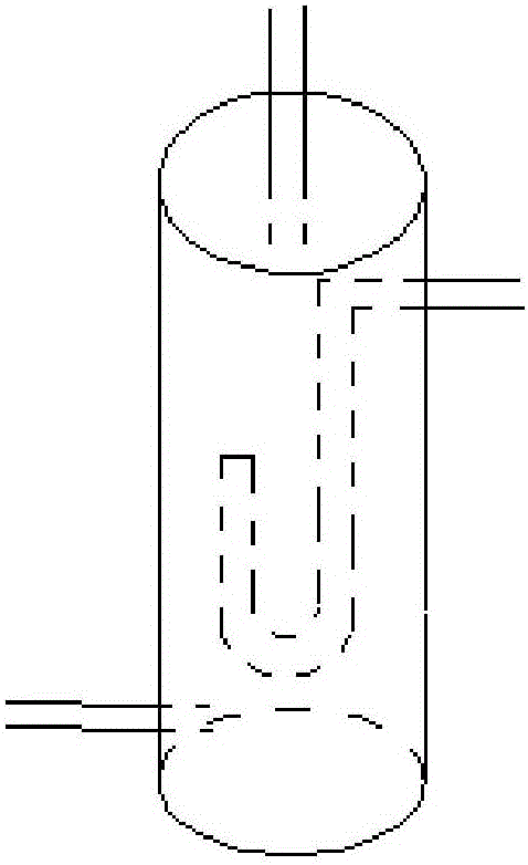
[0041] In the figure: 1-compressor; 2-first four-way valve; 3-first microchannel heat exchanger; 4-first fan; 5-first capillary throttling device; 6-first three-way valve; 7-the second four-way valve; 8-the second capillary throttling device; 9-the second bypass valve; 10-the first gas-liquid separation device; 11-the third capillary throttling device; 12-the second microchannel switch Heater; 13-the second gas-liquid separation device; 14-the first bypass pipe; 15-the second bypass pipe; 16-the second fan; 31-the first flute-type liquid pipe; 121-the second flute-type Dispensing tube.

[0042] The schematic diagram of the system cycle of the present invention is as figure 1 As shown, when used as a refrigeration circuit: the low-temperature and low-pressure refrigerant enters the compressor 1, is compressed to a high-pressure gaseo...


PUM


Abstract

The invention discloses a micro-channel heat pump loop provided with gas-liquid separation devices arranged in front of evaporators. The loop comprises a compressor, a first four-way valve, a first micro-channel heat exchanger (comprising a flute type distribution pipe), a first capillary throttling device, a first by-pass pipe, a first three-way valve, a second four-way valve, a second capillary throttling device, a second by-pass pipe, a second three-way valve, a first gas-liquid separation device, a third capillary throttling device, a second micro-channel heat exchanger (comprising a flute type distribution pipe) and a second gas-liquid separation device, wherein one gas-liquid separation device is arranged in front of each micro-channel heat exchanger used as one micro-channel evaporator, so that a refrigerant entering the micro-channel evaporator is in liquid state, uniform distribution by the aid of the micro-channel evaporator is facilitated, the refrigerating effect of a refrigerating loop is guaranteed, and the heat exchange efficiency is improved.

Description

technical field [0001] The invention belongs to the field of heat pumps, in particular to a microchannel heat pump circuit of a pre-evaporation gas-liquid separation device. Background technique [0002] At present, microchannel heat exchangers are widely used in automotive air conditioners, commercial air conditioners, computer room air conditioners and other fields, mainly as condensers. When traditional microchannel heat exchangers are used as heat pump system evaporators, due to the refrigerant in each flat tube The density of the gas-liquid two-phase refrigerant in the microchannel is different, resulting in very uneven distribution. The phenomenon of "dry evaporation" and "excessive liquid supply" are very common among the microchannels of the flat tubes of the heat exchanger, and the uneven distribution of the refrigerant The uniformity has a great impact on the performance of the system, which greatly reduces the efficiency of the system. [0003] In the traditional...

Claims


Application Information

Patent Timeline
Patent Type & Authority Applications(China)
IPC IPC(8): F25B13/00F25B41/06F25B41/04F25B43/00F25B41/20F25B41/37
CPCF25B13/00F25B43/00F25B2400/23F25B2313/027F25B41/37F25B41/20
Inventor 张忠斌姚喻晨吴琦琦
Owner 浙江豪瓦特节能科技有限公司
Learn More