Control system and method for laser displacement sensor

A control system and laser displacement technology, applied in the field of laser measurement, can solve problems such as unmeasured equipment control, no solution proposed, and influence on measurement results, etc., to reduce cost and energy consumption, low cost and complexity, and improve accuracy degree of effect

Active Publication Date: 2019-05-28
NINGBO SUNNY INTELLIGENT TECH CO LTD +1
View PDF7 Cites 0 Cited by
  • Summary
  • Abstract
  • Description
  • Claims
  • Application Information

AI Technical Summary

Problems solved by technology

However, in this solution, the patent does not involve how to control the working mode of the FPGA
Therefore, the solution disclosed in this patent has the following defects: neither ARM nor FPGA interacts with the measurement equipment, only passively receives and processes data, and cannot control the measurement equipment. If the current working state of the measurement equipment is the actual measurement environment Inconsistency will affect the measurement results, and the effect is poor when applied in large-scale production monitoring scenarios
[0006] For the above problems, no effective solutions have been proposed so far

Method used


Image

  • Control system and method for laser displacement sensor
  • Control system and method for laser displacement sensor
  • Control system and method for laser displacement sensor

Examples


Embodiment Construction

[0053] The description of this illustrative embodiment should be taken in conjunction with the accompanying drawings, which should be considered a part of this complete specification. In the drawings, the shapes or thicknesses of the embodiments may be exaggerated and marked for simplification or convenience. Furthermore, parts of each structure in the drawings will be described separately. It should be noted that elements not shown in the drawings or described in words are forms known to those of ordinary skill in the art.

[0054] The descriptions of the embodiments here, any references to directions and orientations are just for convenience of description, and should not be construed as any limitation to the protection scope of the present invention. Related terms such as "lower", "higher", "horizontal", "vertical", "above", "below", "top", "bottom", "top" and "|bottom" and Derivatives thereof (eg, "horizontally," "downwardly," "upwardly," etc.) should be construed as desc...


PUM


Abstract

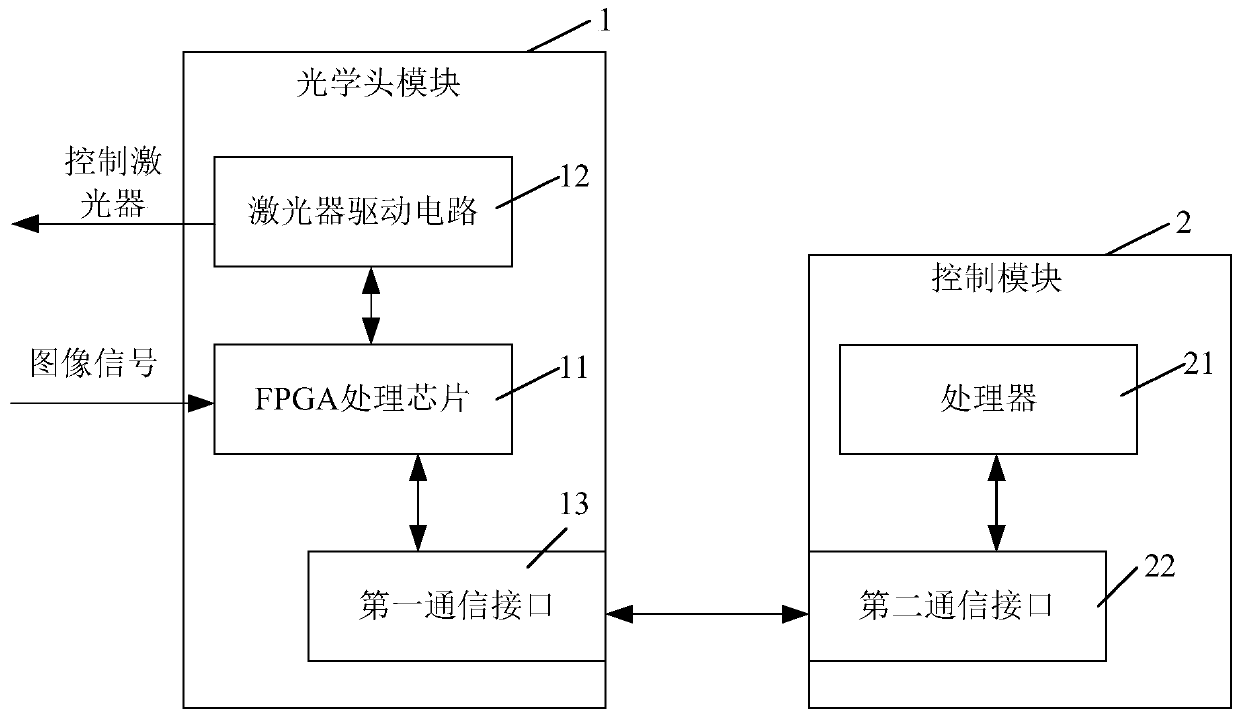
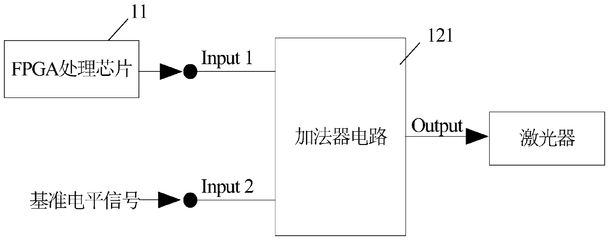
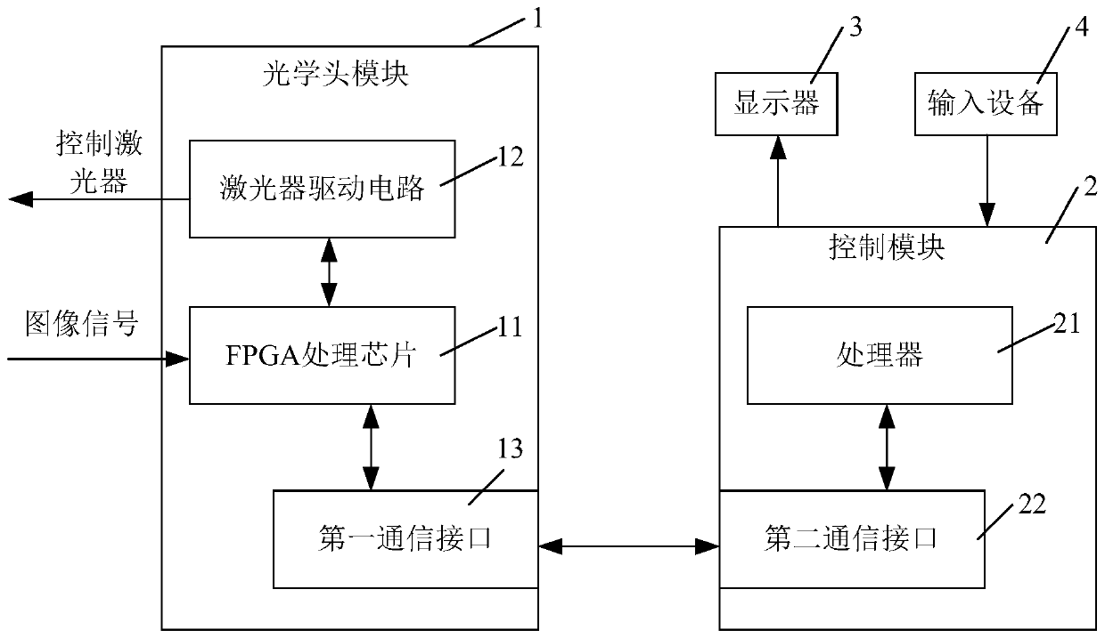
The invention discloses a laser displacement sensor control system and method. The system comprises an optical head module and a control module, wherein the optical head module comprises an FPGA processing chip, a laser drive circuit and a first communication interface; the control module comprises a processor and a second communication interface, wherein the processor and the FPGA processing chip are in communication through a first communication interface and a second communication interface; the FPGA processing chip is used for determining a displacement value according to the image signal from an image sensor, and sending a determined displacement value to a processor, and under the control of the processor, outputs a laser control signal to the laser drive circuit; the laser drive circuit is used for controlling laser work parameters according to the laser control signal; the processor is used for controlling the FPGA processing chip to output the laser control signal and receiving a displacement value from the FPGA processing chip.

Description

technical field [0001] The invention relates to the field of laser measurement, and in particular, to a control system and method for a laser displacement sensor. Background technique [0002] Displacement sensors are components used to measure changes in the position of objects and output the measurement results with digital or analog signals. According to the working principle, displacement sensors can be divided into inductive displacement sensors, capacitive displacement sensors, photoelectric displacement sensors, ultrasonic displacement sensors and Hall displacement sensors. [0003] With its excellent measurement performance, the laser displacement sensor can realize non-contact online measurement of displacement, three-dimensional size, thickness, surface contour, object deformation, vibration, liquid level and other parameters, and can provide effective information for workpiece sorting and installation of various large components. Support (for example, it can assi...

Claims


Application Information

Patent Timeline
Patent Type & Authority Patents(China)
IPC IPC(8): G01B11/02G05B19/042
CPCG01B11/02G05B19/042
Inventor 李颖锋苏庆杰
Owner NINGBO SUNNY INTELLIGENT TECH CO LTD
Why Eureka
Try Eureka