Liquid flow passage box of dynamic magnetic filter

A magnetic filter and liquid flow channel technology, applied in the fields of filtration and separation, chemical instruments and methods, separation methods, etc., can solve the problems of easy sinking of ferromagnetic impurities, no new suspension, low water quality update frequency, etc., and achieve optimization. Use, improve the flow state, reduce the effect of bottom sinking

Active Publication Date: 2017-01-04
BAOSHAN IRON & STEEL CO LTD
View PDF5 Cites 0 Cited by
  • Summary
  • Abstract
  • Description
  • Claims
  • Application Information

AI Technical Summary

Problems solved by technology

[0005] In practical applications, the arrangement of liquid channels formed by the above-mentioned box structure has the following defects: image 3 As shown, after the suspension enters the tank 9 from the tank input pipe 12 to the dirty liquid area 101, and then enters the filter work area 102 from the bottom of the inlet flap 10, it does not disperse and evenly pass through the entire cross section of the filter work area 102 , but will preferentially flow in the direction of the arrow marked in the figure, there will be a "dead zone" for liquid flow in the upper left A region and lower right B region of the filter work area 102, and the "dead zone" for liquid flow is actually Refers to the phenomenon that the liquid flow rate is very slow, that is, the area where the liquid in this area does not change the flow rate correspondingly with the flow state of the liquid at the inlet and outlet
Even if the water quality in this area changes significantly, there is no supplement of new suspension, resulting in too low frequency of water quality renewal
This will lead to: (1) the magnetic rod can only effectively absorb the liquid flow area indicated by the curved arrow, and the adsorption time between the magnetic rod and the suspension is very limited; (2) the availability of the magnetic rod is low, and the upper left The magnetic rod in the part is not effectively put into use before it runs to the lower part; (3) The ferromagnetic impurities in the suspension in the "dead zone" are easy to sink to the bottom, which increases the workload of the operator to manually clean the sediment in the magnetic filter working area on a regular basis
The above drawbacks have greatly weakened the processing effect of the dynamic magnetic rod filter, and the proper processing capacity of the magnetic rod filter has not been effectively utilized.

Method used


Image

  • Liquid flow passage box of dynamic magnetic filter
  • Liquid flow passage box of dynamic magnetic filter
  • Liquid flow passage box of dynamic magnetic filter

Examples


Embodiment Construction

[0030] The specific implementation manners of the present invention will be described in detail below in conjunction with the accompanying drawings of the embodiments.

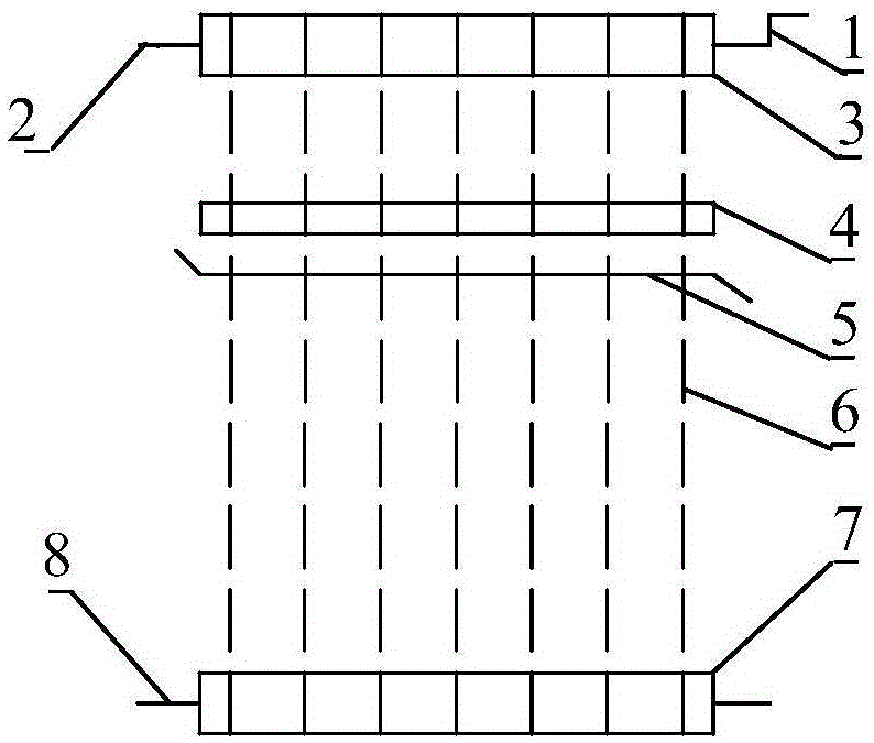
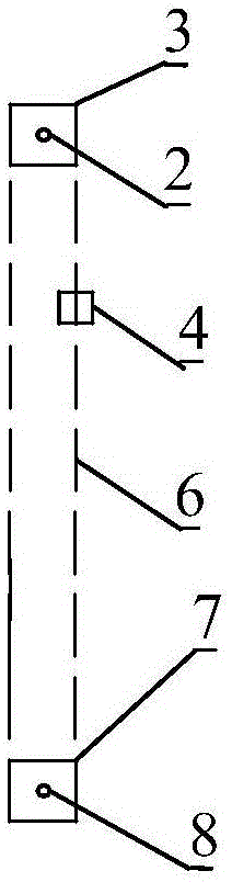
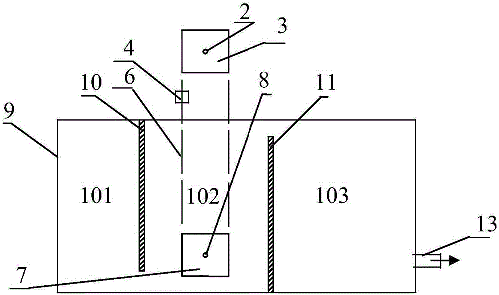
[0031] In the liquid channel box of the dynamic magnetic filter of the present invention, the structure of the dynamic magnetic filter adopts the structure shown in Figure 1, which consists of a driving mechanism 1, a driving shaft 2, a driving wheel 3, and a scraping device 4 , a chip removal groove 5, a multi-section magnetic bar 6, a driven runner 7 and a driven rotating shaft 8; the liquid flow channel box is a rectangular box 25, and the magnetic bar 6 is inserted in the rectangular box 25, The upper end of magnetic bar 6, driving mechanism 1, driving shaft 2, driving runner 3, scraping device 4 and chip removal groove 5 are positioned at above the upper edge of rectangular casing 25, and the top of rectangular casing 25 is open, and its front top is provided with The input pipeline 26 of the suspension i...


PUM

PropertyMeasurementUnit
thicknessaaaaaaaaaa

Abstract

The invention discloses a liquid flow passage box of a dynamic magnetic filter. The liquid flow passage box solves the problem that the existing flow passage box has a liquid magnetic filtering dead region. The liquid flow passage box provided by the invention is characterized in that an inlet turning plate, a middle turning plate and an outlet turning plate are sequentially and separately arranged at the front side and the back side in a rectangular box body; the inlet turning plate, the middle turning plate and the outlet turning plate are provided with openings; the front and back side in the box body is separated into four regions including a foul solution region, a first filtering work region, a second filtering work region and a clean liquid region; the opening of the inlet turning plate and the opening of the outlet turning plate are formed at the inner upper side of the rectangular box body; the opening of the middle turning plate is formed in the inner lower side of the rectangular box body; a plurality of sections of magnetic rods arranged in the rectangular box body form two rows of magnetic chains and are positioned in first and second filtering work regions in a surrounding way; the middle turning plate is arranged between the two rows of magnetic chains and is parallel to the magnetic chains; the inlet turning plate and the output turning plate are symmetrically distributed at the front side and the back side of the middle turning plate. The suspension liquid flow passage flowing through the magnetic rod filter can be optimized; the existence of the liquid magnetic filtering dead region is avoided; the optimization utilization on the magnetic rod filter is realized.

Description

technical field [0001] The invention relates to the field of magnetic filtration, in particular to a liquid channel box of a dynamic magnetic filter. Background technique [0002] Suspensions containing ferromagnetic impurities will be produced in multiple processes of metallurgical production: for example, the steel rolling wastewater in the hot rolling process will contain a large amount of iron oxide scale, and the emulsion in the cold rolling process will carry a large amount of iron powder produced in the rolling process . In order to achieve the purpose of recycling and reducing costs, these suspensions need to be purified and filtered. Magnetic filtration equipment is routinely used, that is, the principle of magnetic adsorption is used to absorb and filter out the magnetic particles in the liquid. [0003] At present, the most common magnetic filter in metallurgical production is the structure of the dynamic magnetic rod filter, as shown in Figure 1: the magnetic ch...

Claims


Application Information

Patent Timeline
Patent Type & Authority Applications(China)
IPC IPC(8): B01D35/06
Inventor 房鑫杨向鹏段明南李山青
Owner BAOSHAN IRON & STEEL CO LTD
Why Eureka
Try Eureka