Motion platform control system of optical detection equipment and control method thereof

A technology of optical detection and motion platform, which is applied in general control system, control/adjustment system, program control in sequence/logic controller, etc. It can solve problems such as high configuration requirements, signal interference, long construction and wiring hours, etc., to achieve The effect of reducing the man-hours of installation, reducing the requirements for configuration, and saving hardware costs

Active Publication Date: 2021-09-03
武汉中导光电设备有限公司
View PDF12 Cites 0 Cited by
  • Summary
  • Abstract
  • Description
  • Claims
  • Application Information

AI Technical Summary

Problems solved by technology

However, a variety of expansion cards are expensive, and the total number often requires more than 10 pieces. The configuration requirements for industrial PCs are also very high, which greatly increases the cost of the electrical control system.
[0005] ②Influence on the performance of industrial PCs, too many expansion cards increase the operating burden of industrial PCs, industrial PCs are prone to abnormalities such as computer blue screens, program freezes and crashes, and the stability of the electrical control system is poor
[0006] ③ The axis control card of the electrical control system needs more than 2 pieces, and the electric cylinder and the Z-axis servo drive are controlled in a pulse mode. The pulse signal cable is more than 10 meters long, which is easily interfered by the signal, and then affects the stability of the axis control. , and the construction wiring takes a long time

Method used


Image

  • Motion platform control system of optical detection equipment and control method thereof

Examples


Embodiment Construction

[0036] In order to make the purpose, technical solution and advantages of the present application clearer, the present invention will be further described in detail below in conjunction with the accompanying drawings and embodiments. It should be understood that the specific embodiments described here are only used to explain the present invention, not to limit the present invention. In addition, the technical features involved in the various embodiments of the present invention described below can be combined with each other as long as they do not constitute a conflict with each other.

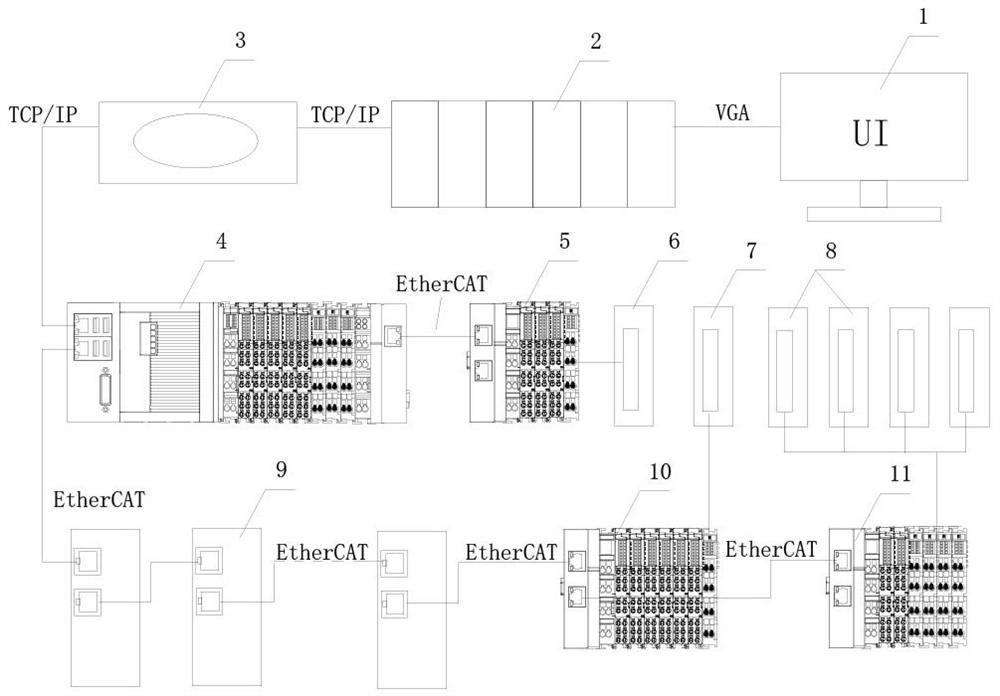
[0037] Such as figure 1 As shown, the present application discloses an embodiment of a motion platform control system for optical detection equipment, and the motion platform control system includes a display 1 and an industrial PC 2 . The motion platform control system includes a PLC master station 4, multiple slave stations and multiple action execution units. The multiple action execution...


PUM


Abstract

The invention discloses a motion platform control system of optical detection equipment and a control method thereof, and relates to the technical field of optical detection, and the motion platform control system comprises a PLC master station, a plurality of slave stations and a plurality of action execution units, the plurality of action execution units are respectively used for carrying out lifting control on a loading ejector rod for placing an object to be detected, controlling a clamp of the optical detection equipment, controlling X-direction movement of the object to be detected, and controlling YZ-direction movement of an optical detection head; the industrial PC is used for operating a UI interface of the display; the industrial PC is respectively connected with the display and the PLC master station; and the PLC master station is connected with all the slave stations. According to the motion platform control system and the control method, the PLC master station and the PLC slave station are introduced into the motion platform control system, so that the cost of the control system is reduced, and the stability of the control system is improved.

Description

technical field [0001] The present application relates to the technical field of optical detection equipment control, in particular to a motion platform control system and control method for optical detection equipment. Background technique [0002] At present, the motion platforms of optical detection equipment on the market are based on industrial PCs. Due to the extremely high precision requirements of the motion platforms for optical detection, electrical components including axis control cards, axis drives controlled by axis control cards, and IO cards are mostly used. control system. Among them, the industrial PC can provide a good UI design, taking into account the motion control and logic control functions of the motion platform. At the same time, the industrial PC can also perform real-time data communication of vision and algorithms to complete the control of the entire electrical control system. [0003] However, the existing electrical control system has obvious...

Claims


Application Information

Patent Timeline
Patent Type & Authority Applications(China)
IPC IPC(8): G05B19/05
CPCG05B19/054G05B2219/13099
Inventor 宋林
Owner 武汉中导光电设备有限公司
Why Eureka
Try Eureka