A method for testing optical fiber stress and strain

A technology of strain testing and optical fiber stress, which is applied in the field of optical fiber production, can solve problems such as low input cost and test deviation, and achieve the effects of reduced input cost, convenient use, and high accuracy

Active Publication Date: 2019-03-15
JIANGSU HENGTONG MARINE CABLE SYST CO LTD
View PDF5 Cites 0 Cited by
  • Summary
  • Abstract
  • Description
  • Claims
  • Application Information

AI Technical Summary

Problems solved by technology

[0004] The purpose of the present invention is to overcome the above problems existing in the prior art, and provide a novel optical fiber stress-strain test method. The test method of the present invention effectively solves the problem of test deviation caused by optical fiber stress changes, and can accurately measure the residual stress in the optical cable. Long, and the input cost is low, effectively controlling the test cost of optical fiber

Method used


Image

  • A method for testing optical fiber stress and strain
  • A method for testing optical fiber stress and strain
  • A method for testing optical fiber stress and strain

Examples


Embodiment

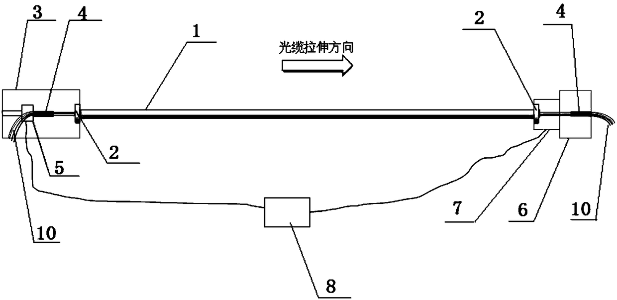
[0028] To carry out optical fiber stress and strain test on the optical cable, first fix the optical cable on the test device, such as figure 2 As shown in , the specific steps are as follows:

[0029] Step 1: Strip off the two ends of the submarine optical cable 1 to expose a section of optical fiber bundle 10 respectively.

[0030] Step 2: Install the cable clamps 2 on both ends of the submarine optical cable, and then clamp the optical cable clamps 3 on the cable fixing pile head 3 and the force value loading pile head 6 respectively. The above optical cable clamps 3 are fixed according to the submarine optical cable and The structure of the pile head is specially made.

[0031] Step 3: Fix the optical fiber bundles at both ends of the submarine optical cable by dispensing glue, one end of which is fixed on the optical fiber tension sensor 5 through the glue dispensing fixing groove 4, the above optical fiber tension sensor 5 is arranged inside the cable fixing pile head ...


PUM


Abstract

The invention discloses an optical fiber stress strain testing method. Two ends of a submarine optical cable are firstly provided with specially-made chucks, the chucks can be clamped on an optical cable fixing pile head and a force loading pile head conveniently, the use is convenient, and the testing efficiency is high. In the case of a drawing test, the end part of an optical fiber bundle is fixed, the optical fiber bundle is not drawn in the optical cable, and inaccurate stress testing can be avoided. A high-precision optical fiber tension sensor and a high-precision optical cable drawing force sensor are adopted, an accurate testing result can be acquired. During the testing process, an optical fiber tension value and an optical cable drawing force value can be monitored in real time and recorded, the accuracy of a curve after final linear fitting is high, the problem of test deviation caused by optical fiber stress changes can be effectively solved, and the excess length in the optical cable can be accurately tested. The R2 of the fit curve is tested to be 0.9915 in the traditional time delay method, the R2 of the fit curve in the method of the invention is 0.9984, and after comparison, data obtained by the optical fiber stress strain testing method is higher in reliability.

Description

technical field [0001] The invention relates to the technical field of optical fiber production, in particular to optical fiber performance testing, in particular to an optical fiber stress and strain testing method. Background technique [0002] The design of the excess length of the submarine optical cable is related to the stress value of the optical fiber when the submarine cable is stressed during construction. Too small excess length design may cause the optical fiber to be too pulled and break when the cable is stressed. It may lead to an increase in the macrobending loss of the optical fiber in the cable, so it is very important to accurately evaluate the excess length of the optical fiber in the submarine optical cable for the design of the submarine optical cable. [0003] At present, the more common method for testing the excess length of submarine optical cables is to use a dispersion tester to monitor the micro-delay change of the optical signal in the optical f...

Claims


Application Information

Patent Timeline
Patent Type & Authority Patents(China)
IPC IPC(8): G01M11/02
CPCG01M11/02
Inventor 蒋寅查尔斯.杰里米.布朗朱志高徐婷冯富许人东孙贵林孙晓华
Owner JIANGSU HENGTONG MARINE CABLE SYST CO LTD
Why Eureka
Try Eureka