Backlight module and liquid crystal display device
A liquid crystal display device and backlight module technology, which is applied in the fields of optics, nonlinear optics, instruments, etc., can solve the problems of unfavorable narrow-edge design of liquid crystal display devices, increase the side width distance of front frame arms, etc., and achieve a reduction in display Uneven, conducive to narrowing the edge, reducing the effect of width space
- Summary
- Abstract
- Description
- Claims
- Application Information
AI Technical Summary
Problems solved by technology
Method used
Image

Examples
Embodiment 1
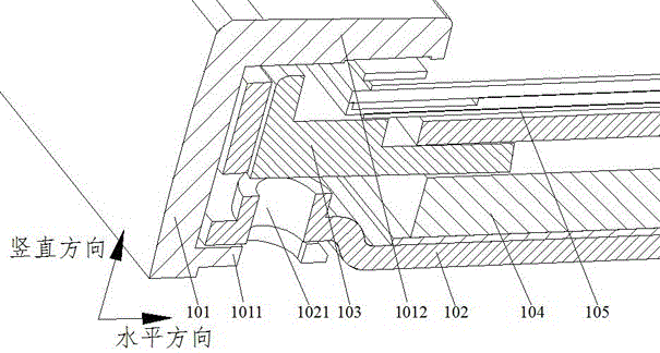
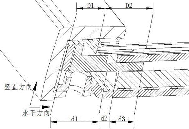
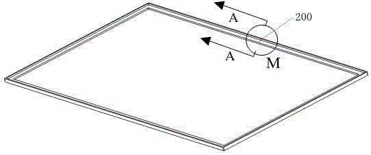
[0056] This embodiment provides a liquid crystal display device. The overall structural diagram of the liquid crystal display device in this embodiment is shown in image 3 As shown, the partial enlarged structural cross-sectional view of the liquid crystal display device in the M region along the A direction is shown as Figure 4 shown. The liquid crystal display device mentioned in this embodiment includes: a backlight module 200 and a panel 205 , wherein the backlight module 200 includes: a front frame 201 , a back plate 202 , a plastic frame 203 and a light guide plate 204 .
[0057] Wherein, the back plate 202 includes a bottom plate 2022 and a vertical plate 2021 surrounding the edge of the bottom plate 2022, and the bottom plate 2022 is used to place the light guide plate 204, and a sliding button is protruded from the outer surface of the vertical plate 2021; the front frame 201 includes a side wall 2011, the inner side of the side wall 2011 is provided with a slidewa...
Embodiment 2
[0084] This embodiment provides a backlight module. The backlight module is the backlight module mentioned in Embodiment 1 in the liquid crystal display device. The specific structural diagram of the backlight module 200 is as follows Figure 11 As shown, the backlight module 200 includes: a front frame 201 , a back plate 202 , a plastic frame 203 and a light guide plate 204 .
[0085] The purpose of this embodiment is to provide a new fixing method of the front frame 201 and the back plate 202 in the backlight module, and change the screw fixing method of the front frame and the back plate in the prior art to a fixing method of slide rails, This fixing method can save the width distance occupied by the fixing screws, and the sliding buckle fixing design of the slideway is a screwless design, which can make full use of the existing space in the height direction of the side wall of the front frame and the back panel vertical plate, saving The structure of the locking screws on ...
Embodiment 3
[0087] Different from the method of fixing the backplane 202 and the front frame 201 in the first embodiment, which is a slideway slide button connection, the purpose of this embodiment is to provide another way of fixing the backplane and the front frame.
[0088] The partial structural diagram of the backplane in this embodiment is as follows Figure 12 As shown, the back plate 301 includes a vertical plate 3012 and a bottom plate 3011, the vertical plate 3012 is set perpendicular to the bottom plate 3011, and a first column 3013 is set on the outer surface of the vertical plate 3012, and the number of the first column 3013 can be one or more , open in pairs on the outer surface of the vertical plate 3012, set up the second column 3014 on the top surface of the first column 3013, the cross-sectional area of the second column 3014 is greater than the cross-sectional area of the first column 3013, the second column 3014 The top surface is chamfered so that the outer surfac...
PUM
 Abstract
Description
Claims
Application Information
 - R&D
- Intellectual Property
- Life Sciences
- Materials
- Tech Scout
- Unparalleled Data Quality
- Higher Quality Content
- 60% Fewer Hallucinations
Browse by: Latest US Patents, China's latest patents, Technical Efficacy Thesaurus, Application Domain, Technology Topic, Popular Technical Reports.
© 2025 PatSnap. All rights reserved.Legal|Privacy policy|Modern Slavery Act Transparency Statement|Sitemap|About US| Contact US: help@patsnap.com