Touch display panel and driving method thereof, touch display device

A technology of touch display panel and touch display device, which is applied in the direction of instruments, electrical digital data processing, and input/output process of data processing, etc., and can solve problems such as inability to receive directly, complicated driving methods, and poor pressure-sensitive detection effects, etc. problem, to achieve the effect of high precision and simplified driving mode

Active Publication Date: 2016-11-16
XIAMEN TIANMA MICRO ELECTRONICS +1
View PDF5 Cites 8 Cited by
  • Summary
  • Abstract
  • Description
  • Claims
  • Application Information

AI Technical Summary

Problems solved by technology

[0004] However, the driving method of the existing touch display panel to realize pressure sensing is relatively complicated. In a period of time, it is necessary to first obtain the signal amount of touch sensing, and then obtain the total signal amount of touch sensing and pressure sensing, and then obtain the total signal amount of touch sensing and pressure sensing. Through algorithm processing, indirectly obtain the semaphore of pressure sensing detection
It can be seen that this driving method cannot directly receive the semaphore of pressure detection, and the effect of pressure detection is not good.

Method used


Image

  • Touch display panel and driving method thereof, touch display device
  • Touch display panel and driving method thereof, touch display device
  • Touch display panel and driving method thereof, touch display device

Examples


no. 1 example

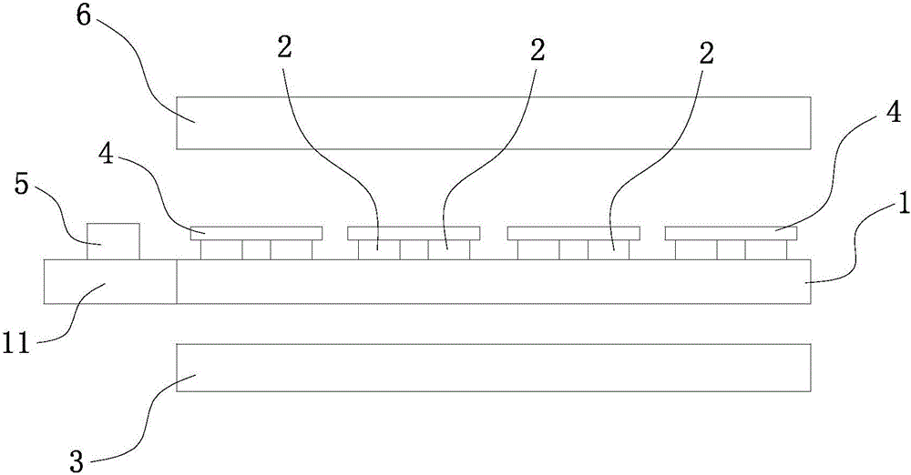
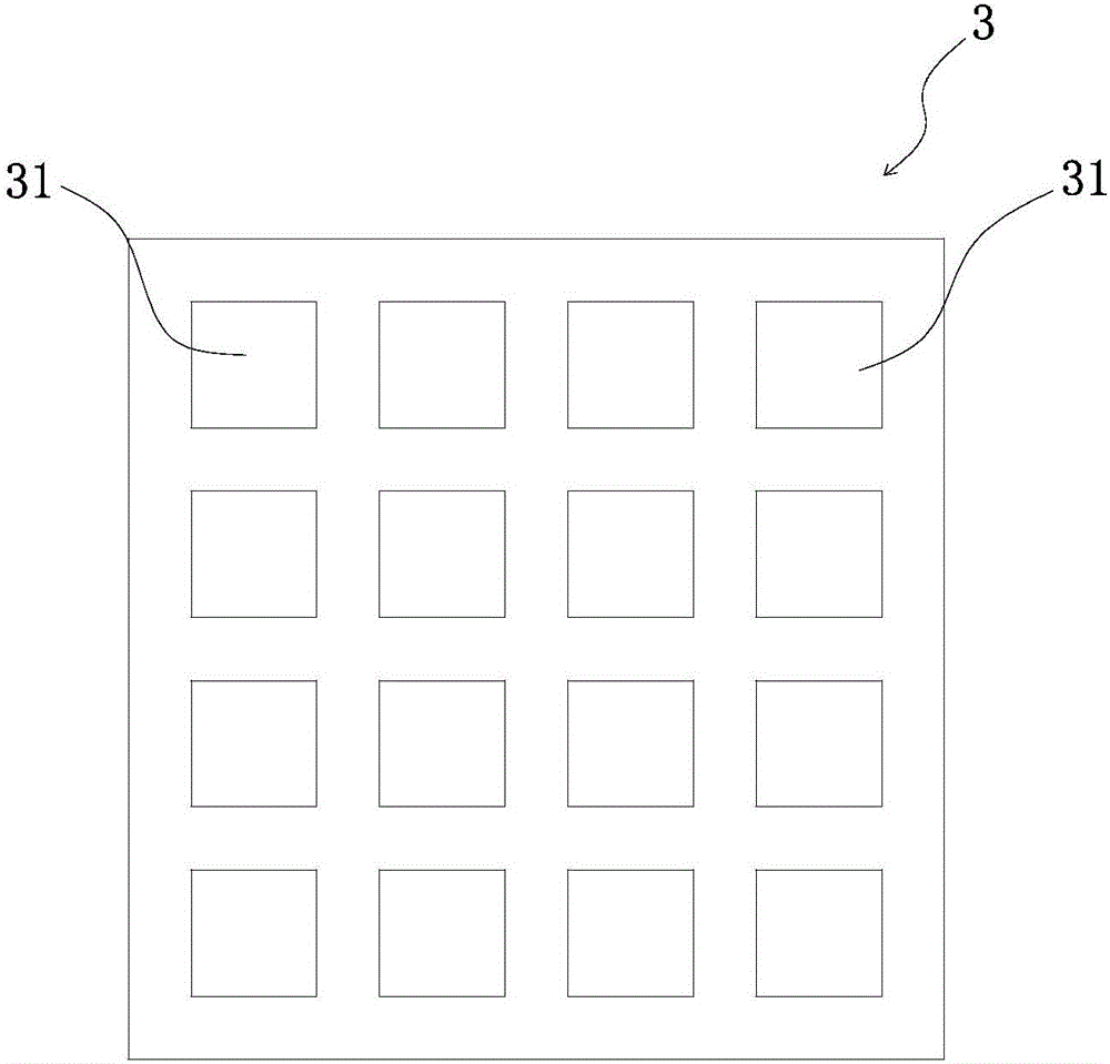
[0019] Please also see figure 1 and figure 2 , which respectively show a schematic cross-sectional structure diagram of the touch display panel and a structural schematic diagram of the pressure-sensitive detection layer of the touch display panel according to the first embodiment of the present invention. Such as figure 1 As shown, in an optional embodiment of the present invention, the touch display panel may be a touch liquid crystal display panel or a touch OLED display panel. The touch display panel includes a first substrate 1 , a plurality of gate signal lines 2 and a pressure sensing layer 3 .

[0020] exist figure 1 In the illustrated embodiment, the first substrate 1 is optionally an array substrate. A plurality of gate signal lines 2 are disposed on the first substrate 1 . Such as figure 1 As shown, a plurality of gate signal lines 2 are arranged parallel to each other on the first substrate 1 . In the embodiment of the present invention, the gate signal lin...

no. 2 example

[0036] The second embodiment of the present invention is another implementation of the touch display panel of the present invention, please refer to Figure 4 , which shows a schematic structural diagram of the pressure-sensitive detection layer of the touch display panel according to the second embodiment of the present invention. with the above figure 2 The difference of the first embodiment shown is that in this embodiment, the pressure sensing layer 3 includes a plurality of strips along the first direction ( Figure 4 The first electrodes 31' arranged along the X-axis direction). Specifically, as Figure 4 As shown, a plurality of first electrodes 31' are strip-shaped, and each first electrode 31' is along the second direction ( Figure 4 Extending along the Y-axis direction), a plurality of first electrodes 31' are arranged along a first direction, wherein the first direction is perpendicular to the second direction, and the first direction is consistent with the ext...

no. 3 example

[0039] The third embodiment of the present invention is another implementation of the touch display panel of the present invention, please refer to Figure 5 , which shows a schematic structural diagram of the pressure-sensitive detection layer of the touch display panel according to the third embodiment of the present invention. with the above figure 2 The difference of the first embodiment shown is that in this embodiment, the pressure-sensitive detection layer 3 includes a first electrode 31" corresponding to the size of the area where the plurality of gate signal lines 2 are located. Specifically, as Figure 5 As shown, the pressure-sensitive detection layer 3 is only formed by a large-sized first electrode 31" corresponding to the area where the plurality of gate signal lines 2 are located (ie, the display area of ​​the touch display panel). This embodiment can realize the above-mentioned figure 1 and figure 2 The first embodiment shown has a similar effect, and since...


PUM


Abstract

The invention discloses a touch display panel and a driving method thereof and a touch display device. The touch display panel comprises a first substrate, multiple grate signal wires arranged on the first substrate and reused as grate scanning wires and pressure driving wires when the grate signal wires are divided, a pressure testing layer used for receiving pressure testing signals when the grate signal wires are configured as the pressure driving wires so that pressure magnitude can be detected according to capacitance changes between the grate signal wires and the pressure testing wires. The touch display panel has a pressure testing function so that detection of external pressure by the touch display panel can be achieved. The touch display panel and the driving method thereof can directly obtain signal amount of pressure testing and optimize pressure testing effect.

Description

technical field [0001] The present invention relates to the field of display technology, in particular to a touch display panel, a driving method for the touch display panel, and a touch display device with the touch display panel. Background technique [0002] With the rapid development of display technology, touch display panels have gradually spread in people's lives. Especially with the emergence of the pressure sensing technology, the touch display panel can sense the strength of light pressure and heavy pressure, and call out different corresponding functions, so that the touch display panel has more applicability. [0003] In the existing touch display panel, in order to realize the function of pressure sensing, a plurality of first common electrodes disposed on the array substrate are usually used, and the first common electrodes are multiplexed as touch electrodes and pressure sensing electrodes. That is, during the touch sensing period, the first common electrode ...

Claims


Application Information

Patent Timeline
Patent Type & Authority Applications(China)
IPC IPC(8): G06F3/041G06F3/044
CPCG06F3/0412G06F3/0414G06F3/044
Inventor 孙莹邹宗骏黄敏许育民
Owner XIAMEN TIANMA MICRO ELECTRONICS
Why Eureka
Try Eureka