Laser beam quality control method for ultra-multi-pass amplification system

A technology of laser beam quality and amplifying system, applied in the field of laser beam quality control of super multi-pass amplifying system, can solve the problems of serious aberration accumulation effect of amplifying pulses, and the beam quality is not significantly improved, so as to avoid the problem of aberration accumulation, Effective light transmission, low cost effect

Inactive Publication Date: 2016-11-16
LASER FUSION RES CENT CHINA ACAD OF ENG PHYSICS
View PDF5 Cites 7 Cited by
  • Summary
  • Abstract
  • Description
  • Claims
  • Application Information

AI Technical Summary

Problems solved by technology

In order to increase the gain multiple of the amplifier, super multi-pass amplification technology is adopted (Design and optimization of an adaptive optics system for a high-average-power multi-slab laser, "Applied Optics", Vol.53, 2014, 3255-3261), Due to the serious aberration accumulation effect of the amplified pulse in this technology, the beam quality has not been significantly improved after aberration correction using the current beam quality control method

Method used


Image

  • Laser beam quality control method for ultra-multi-pass amplification system
  • Laser beam quality control method for ultra-multi-pass amplification system
  • Laser beam quality control method for ultra-multi-pass amplification system

Examples


Embodiment 1

[0039] A method for controlling the quality of a laser beam in an ultra-multipass amplification system, comprising the following steps:

[0040] S 1 : measuring the internal aberration of the amplifying cavity, and correcting the internal aberration;

[0041] S 2 : measuring the total optical path aberration, and correcting the total optical path aberration.

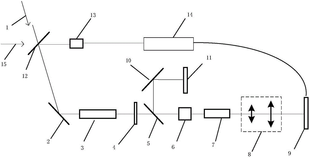
[0042] The super multi-pass amplification system such as figure 1As shown, the beam aperture of laser 1 is 8×8mm, the wavelength is 1053nm, the pulse width is 3ns, p-state polarized light, the parameters of the calibration light 15 are the same as those of laser 1, and the mirror 1 has a high reflectivity for laser 1. The diameter of the standard flat mirror 4 is 20×20mm, and it has high reflectivity to 1053nm laser 1, and the beam splitter 15 has high transmittance to p-state polarized light, and high reflectivity to s-state polarized light, and the size of laser amplifying medium 7 is 12× 12×30mm, the beam expansio...

Embodiment 2

[0059] The same part of this embodiment and Embodiment 1 will not be repeated, the difference is:

[0060] The beam diameter of laser 1 is 10×10mm, the wavelength is 1053nm, the pulse width is 1ns, p-state polarized light, the size of laser amplification medium 7 is 15×15×40mm, and the beam expansion ratio of spatial filter system 8 is 1:6. The diameter of the cavity mirror 11 is 20×20 mm, and the wavefront corrector 9 is a piezoelectric film-driven deformable mirror, and its parameters are shown in Table 3:

[0061]

[0062] , the wavefront detector 13 is a Hartmann wavefront sensor, and its parameters are as shown in Table 4:

[0063]

[0064]

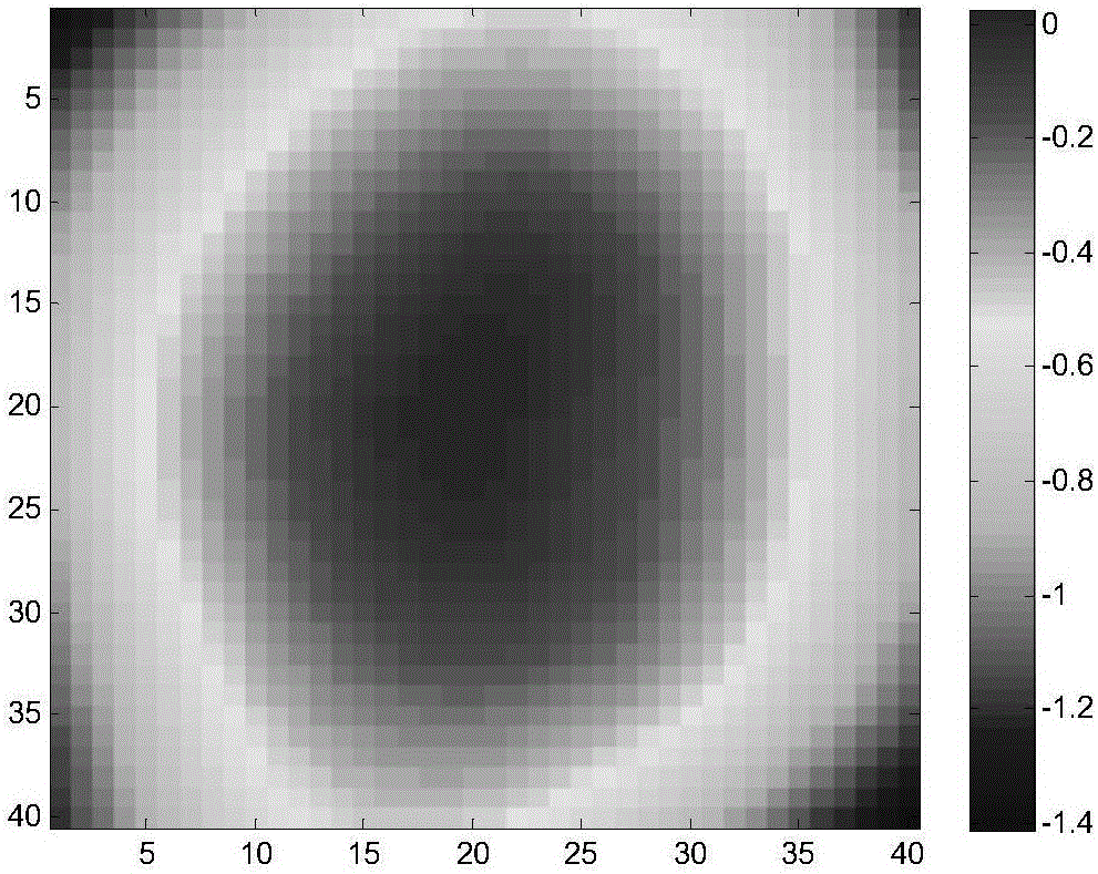
[0065] In this embodiment, the amplification system is an eight-pass amplification, and the optical path aberration W outside the amplification cavity is measured 1 , and its corresponding wavefront distribution is shown in Figure 4 As shown, the wavefront distortion is 0.42 wavelength; when the laser optical path is doub...


PUM


Abstract

The invention relates to a laser beam quality control method for an ultra-multi-pass amplification system, and belongs to the technical field of laser equipment. The laser beam quality control method comprises the steps of measuring internal aberration of an amplification cavity, and correcting the internal aberration; and measuring the aberration of a full light path, and correcting the aberration of the full light path. According to the method, the aberration correction is carried out in different steps; compared with the one-step correction method in the prior art, the laser beam quality control method provided by the invention can avoid the problem of multi-pass amplification aberration accumulation, and the optimal wave-front correction effect can be achieved, so that the laser beam quality control method is applicable to the ultra-multi-pass amplification laser beam quality control.

Description

technical field [0001] The invention belongs to the technical field of laser equipment, and in particular relates to a method for controlling the quality of a laser beam in a super multi-pass amplification system. Background technique [0002] Multi-pass amplification technology has been widely used in the energy amplification of laser pulses, which greatly simplifies the structure of the amplification optical path. However, the optical components in the optical path and the heat-pumped laser amplification medium will cause wavefront distortion, which seriously affects the smooth realization of the optical pulse amplification process and the beam quality after pulse amplification. [0003] In order to overcome the negative effects of optical distortion, adaptive optics technology is applied to amplification technology (Adaptiveoptics-a progress review, "Proc. SPIE", Vol.1542, 1991, 2-17). To put it simply, the wavefront distortion of the laser pulse during the amplification...

Claims


Application Information

Patent Timeline
Patent Type & Authority Applications(China)
IPC IPC(8): H01S3/00H01S3/23
CPCH01S3/005H01S3/0071H01S3/2325
Inventor 薛峤代万俊胡东霞王德恩杨英张鑫袁强赵军普张晓璐曾发高松姚轲谢旭东
Owner LASER FUSION RES CENT CHINA ACAD OF ENG PHYSICS
Why Eureka
Try Eureka