A method for controlling the quality of laser beams in an ultra-multipass amplification system
A technology of laser beam quality and amplifying system, applied in the field of laser beam quality control of ultra-multi-pass amplifying system, can solve the problems of not significantly improving beam quality, serious aberration accumulation effect of amplified pulse, etc. Effective light transmission, low cost effect
- Summary
- Abstract
- Description
- Claims
- Application Information
AI Technical Summary
Problems solved by technology
Method used
Image
Examples
Embodiment 1
[0039] A method for controlling the quality of a laser beam in an ultra-multipass amplification system, comprising the following steps:
[0040] S 1 : measuring the internal aberration of the amplifying cavity, and correcting the internal aberration;
[0041] S 2 : measuring the total optical path aberration, and correcting the total optical path aberration.
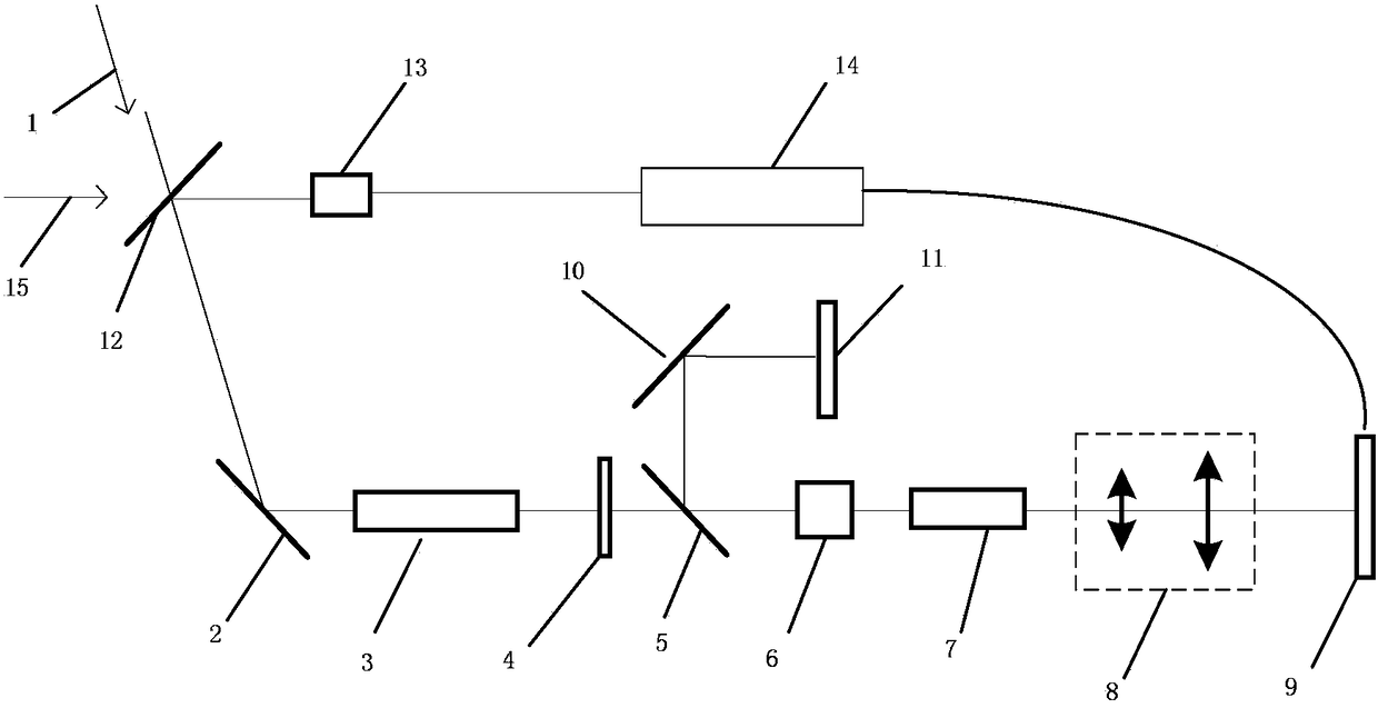
[0042] The super multi-pass amplification system such as figure 1As shown, the beam aperture of laser 1 is 8×8mm, the wavelength is 1053nm, the pulse width is 3ns, p-state polarized light, the parameters of the calibration light 15 are the same as those of laser 1, and the mirror 1 has a high reflectivity for laser 1. The diameter of the standard flat mirror 4 is 20×20mm, and it has high reflectivity to 1053nm laser 1, and the beam splitter 15 has high transmittance to p-state polarized light, and high reflectivity to s-state polarized light, and the size of laser amplifying medium 7 is 12× 12×30mm, the beam expansio...
Embodiment 2
[0059] The same part of this embodiment and Embodiment 1 will not be described again, the difference is:
[0060] The beam diameter of laser 1 is 10×10mm, the wavelength is 1053nm, the pulse width is 1ns, p-state polarized light, the size of laser amplification medium 7 is 15×15×40mm, and the beam expansion ratio of spatial filter system 8 is 1:6. The diameter of the cavity mirror 11 is 20×20 mm, and the wavefront corrector 9 is a piezoelectric film-driven deformable mirror, and its parameters are shown in Table 3:
[0061]
[0062] , the wavefront detector 13 is a Hartmann wavefront sensor, and its parameters are as shown in Table 4:
[0063]
[0064]
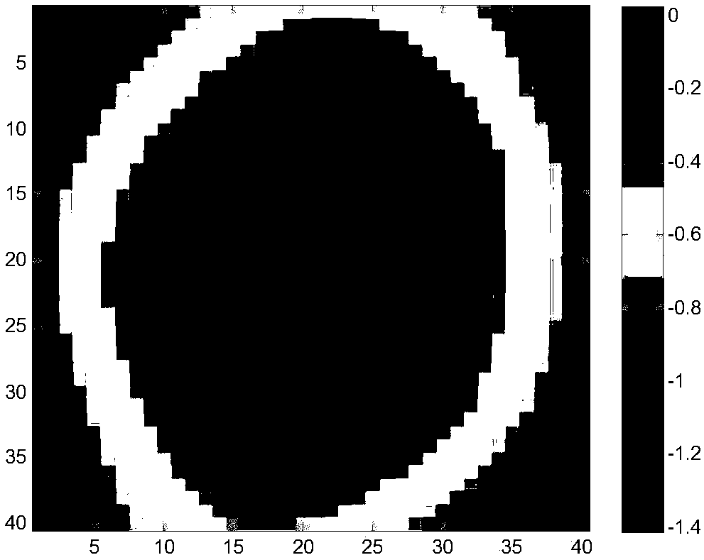
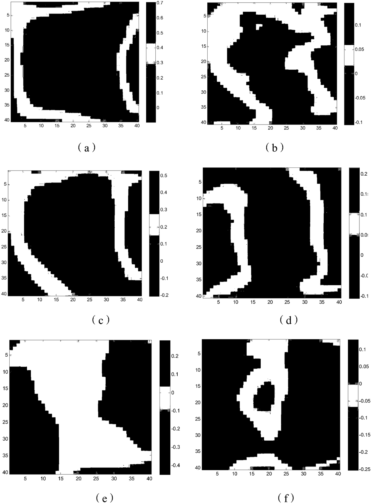
[0065] In this embodiment, the amplification system is an eight-pass amplification, and the optical path aberration W outside the amplification cavity is measured 1 , and its corresponding wavefront distribution is shown in Figure 4 As shown, the wavefront distortion is 0.42 wavelength; when the laser optical path ...
PUM
 Abstract
Description
Claims
Application Information
 - R&D
- Intellectual Property
- Life Sciences
- Materials
- Tech Scout
- Unparalleled Data Quality
- Higher Quality Content
- 60% Fewer Hallucinations
Browse by: Latest US Patents, China's latest patents, Technical Efficacy Thesaurus, Application Domain, Technology Topic, Popular Technical Reports.
© 2025 PatSnap. All rights reserved.Legal|Privacy policy|Modern Slavery Act Transparency Statement|Sitemap|About US| Contact US: help@patsnap.com


