hydraulic winch

A hydraulic winch and winch technology, applied in the direction of hoisting device, spring mechanism, etc., can solve the problem of increasing the space of the winch, limiting the improvement of the winch's on-board capacity, affecting the life of the wire rope, etc. Convenience, weight reduction effect

Inactive Publication Date: 2005-12-28
中国人民解放军总装备部装甲兵装备技术研究所
View PDF0 Cites 2 Cited by
  • Summary
  • Abstract
  • Description
  • Claims
  • Application Information

AI Technical Summary

Problems solved by technology

In addition, the reducer of the existing winch is installed side by side with the friction roller in the axial direction, but the internal space of the friction roller is not used, resulting in a large axial dimension of the winch, which increases the space requirement of the winch when installed in the car. Require
[0003] The above factors increase the production cost of the winch, seriously affect the life of the wire rope, restrict the installation of the winch in the car, and greatly limit the improvement of the winch's vehicle performance.

Method used


Image

  • hydraulic winch
  • hydraulic winch
  • hydraulic winch

Examples


Embodiment Construction

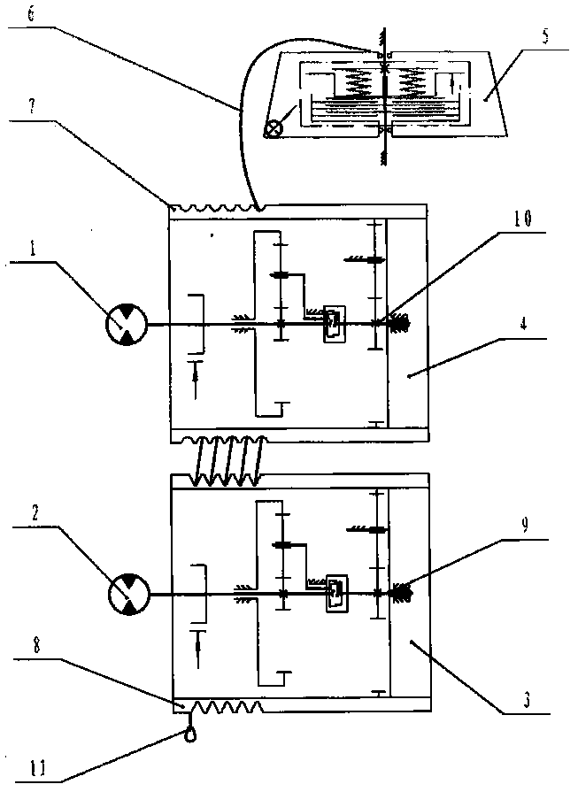
[0017] The mechanical transmission diagram of the hydraulic winch of the present invention is shown in figure 1 , consists of winch power device and rope storage device 5, and the two are connected by guide rail 6. The winch power device is mainly composed of motor 1, motor 2, front friction drum assembly 4, and rear friction drum assembly 3. There are rope grooves on the two friction drum assemblies, and the steel wire rope 11 forms the same winding direction along the outer side of the second friction drum assembly. Through each rope groove in turn, the two friction roller assemblies are connected together, and the friction force between the roller rope groove and the wire rope is used to transmit the motor 1 and motor 2 to the front friction roller 7 and the rear friction roller 7 through the reducer 9 and the reducer 10. The torque of the friction drum 8 is converted into the pulling force on the wire rope 11 to realize the constant pulling force output of the winch. The ...


PUM


Abstract

A hydraulic winch is composed of two parts: a winch power device and a rope storage device. connected by wire rope. The internal structure of the two friction drum assemblies is the same, and the planetary reducer and hydraulic brake are placed inside the friction drum, and the planetary reducer is connected with the gear shift cylinder, so as to realize the work of retracting and releasing the rope under load and no load. The rope storage drum used to store the steel wire rope is a coiled rope storage device. The winch has the advantages of simple structure, light weight, low cost and convenient arrangement in the vehicle, etc., and can be used for self-rescue, mutual rescue or pulling heavy objects on the motor vehicle along with the vehicle.

Description

1. Technical field [0001] The invention relates to a coiled winch driven by a hydraulic motor, which belongs to vehicle rescue equipment and is mainly used for dragging and rescuing vehicles that are silted, overturned or dropped into ditch. 2. Background technology [0002] The constant tension winches used on the existing equipment of our army are all winding winches. The volume and weight of the coiled rope storage device are relatively large, usually accounting for nearly half of the entire winch; the rope storage device needs the power device of the winch to provide power, so it must be installed close to the power device of the winch; The drum will not be loose, and the rope storage device must maintain a slipping torque of at least 343N·m, so that the steel wire rope is always in a squeezed state on the rope storage drum. In addition, the reducer of the existing winch is installed side by side with the friction roller in the axial direction, but the internal space of...

Claims


Application Information

Patent Timeline
Patent Type & Authority Patents(China)
IPC IPC(8): B66D1/08B66D1/24
Inventor 李晓明孙吉生
Owner 中国人民解放军总装备部装甲兵装备技术研究所
Why Eureka
Try Eureka