Abrasion drill for surgery

A technology for surgical and grinding drills, which is applied in the fields of surgery and medical science, can solve the problems of single grinding and drilling effects, large instantaneous grinding amount, and large wound surface, etc., and achieves a simple structure, good safety, and convenient operation. Effect

Active Publication Date: 2016-11-23
贵州梓锐科技有限公司
View PDF8 Cites 4 Cited by
  • Summary
  • Abstract
  • Description
  • Claims
  • Application Information

AI Technical Summary

Problems solved by technology

[0002] Surgical drills usually use the unidirectional rotation of the cutter head to grind bone tissue. The unidirectional rotation makes the instantaneous grinding amount of the cutter head to the bone tissue larger, the wound surface is larger, and the recovery of bone tissue is slower; , the commonly used surgical drill has a single effect, the directionality of the grinding position is relatively fixed, the adjustment is demanding, the precision is poor, and the grinding effect on complex bone tissue is not good

Method used


Image

  • Abrasion drill for surgery
  • Abrasion drill for surgery
  • Abrasion drill for surgery

Examples


Embodiment 1

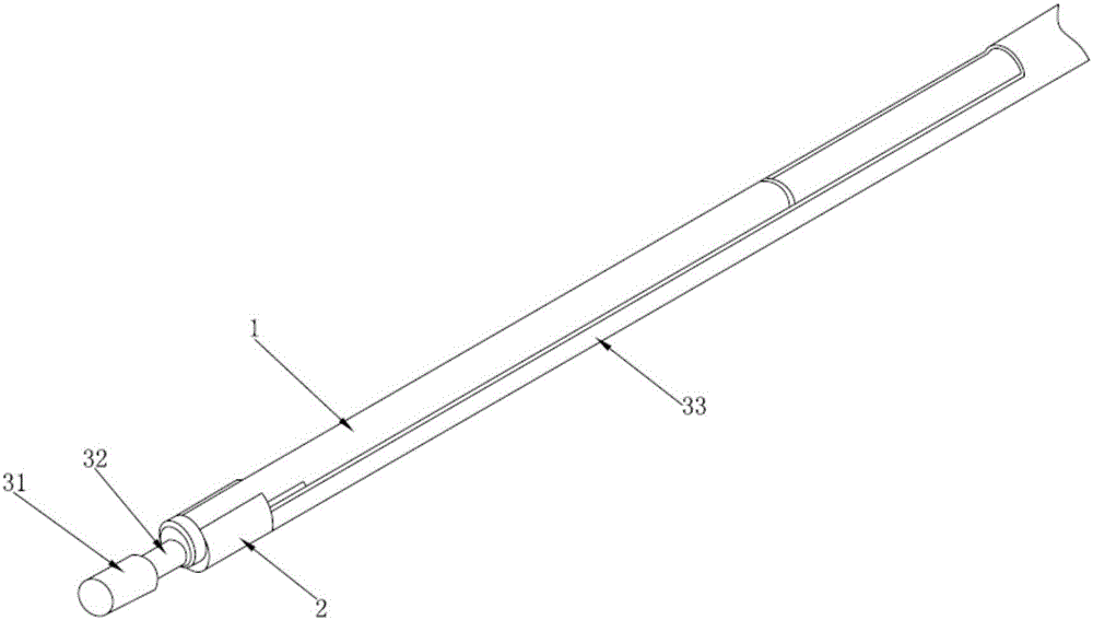
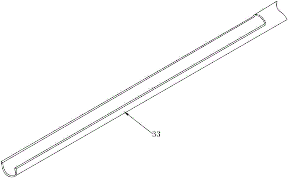
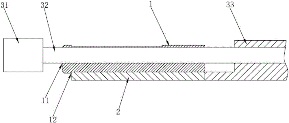
[0033] Depend on figure 1 , figure 2 and image 3 As shown, the present invention is composed of a grinding head 31 and a knife tube 33, etc., the grinding head 31 is provided with a grinding handle 32, and the end of the knife tube 33 near the grinding head 31 is provided with an inner support body 1 and an outer support body 2 The double-layer structure, the grinding handle 32 passes through the inner support body 1, the inner support body 1 is provided with the first eccentric hole 11, and the grinding handle 32 is set in the first eccentric hole 11; the outer The support body 2 is provided with a second eccentric hole 21, the inner support body 1 is sleeved in the second eccentric hole 21, the outer circle of the inner support body 1 and the inner diameter of the second eccentric hole 21 cooperate; the outer support body A section of opening is provided on the side of the body 2 close to one end of the grinding head 31 , and the second eccentric hole 21 is connected thr...

Embodiment 2

[0037] Such as figure 1 , figure 2 and Figure 4 As shown, the difference from Example 1 is that the inner support body 1 is provided with a first oblique hole 12, and the grinding handle 32 is penetrated in the first oblique hole 12; the outer support body 2 is provided with a second oblique hole 22. The inner support body 1 is sleeved in the second slanted hole 22, and the outer circle of the inner support body 2 and the inner diameter of the second slanted hole 22 match.

[0038] When in use, the design of the inclined hole can make the grinding handle 32 with soft material adjustable in direction, and at the same time make the protruding grinding head 31 have a parallel or oblique grinding angle, so that the space can be used in a wider range. Two support bodies The outer diameter of the first slanted hole 12 and the inner diameter of the second slanted hole 22 cooperate with each other to meet the rotation requirements between the two supports, avoid interference durin...


PUM


Abstract

The invention discloses an abrasion drill for surgery. The abrasion drill comprises an abrasion head (31) and a knife tube (33), an abrasion handle (32) is arranged on the abrasion head (31), a bilayer structure of an inner supporting body (1) and an outer supporting body (2) is arranged at one end, close to the abrasion head (31), of the knife tube (33), the abrasion handle (32) penetrates the inner supporting body (1), and the inner supporting body (1) and the outer supporting body (2) can rotate relatively and can change position of axis of the abrasion handle (32) relative to the outer supporting body (2). Under action of driving force of the outer supporting body, the inner supporting body which is arranged eccentrically and the abrasion head and joint action of a limiting device and a reciprocating device, the abrasion head is enabled to reciprocatingly abrade bone tissue, so that abrasion quantity is controlled effectively, convenience is brought to adjusting abrasion position and direction, and the abrasion drill is simple in structure, convenient and quick to operate and high in stability and safety.

Description

technical field [0001] The invention relates to the technical field of bone tissue grinding tools, in particular to a surgical drill. Background technique [0002] Surgical drills usually use the unidirectional rotation of the cutter head to grind bone tissue. The unidirectional rotation makes the instantaneous grinding amount of the cutter head to the bone tissue larger, the wound surface is larger, and the recovery of bone tissue is slower; , the commonly used surgical drill has a single effect, the directionality of the grinding position is relatively fixed, the adjustment requirements are high, the precision is poor, and the grinding effect on complex bone tissue is not good. Contents of the invention [0003] The technical problem to be solved by the present invention is to provide a surgical burr that can not only effectively control the grinding amount, but also facilitate adjustment of the grinding position and direction. [0004] Technical scheme of the present i...

Claims


Application Information

Patent Timeline
Patent Type & Authority Applications(China)
IPC IPC(8): A61B17/16A61B17/56
CPCA61B17/16A61B17/1626A61B2017/1602A61B2017/564
Inventor 彭惠莲
Owner 贵州梓锐科技有限公司
Why Eureka
Try Eureka