
Orthopedic locking screw

A locking screw, orthopedic technology, applied in the field of orthopedic medical devices, can solve the problems of reducing the contact area, unfavorable bone healing in the circumference, inconvenient stress dispersion, etc.

Inactive Publication Date: 2016-11-23
张立沼
View PDF6 Cites 7 Cited by
  • Summary
  • Abstract
  • Description
  • Claims
  • Application Information

AI Technical Summary

Problems solved by technology

Therefore, the AO organization launched the limited contact dynamic compression plate, that is, the LC-DCP plate, which can reduce the extensive stripping of soft tissues during the operation, reduce the contact area between the plate and the bone surface, reduce blood supply damage, and benefit fractures. However, it was gradually discovered that the LC-DCP plate could not satisfy the perfect formation of callus at the fracture site, and the formation of callus was discontinuous and asymmetrical.
So far, after the existing locking screw is matched with the LC-DCP plate, the screw cannot move slightly with the screw hole, which is not convenient for stress dispersion, which is not conducive to promoting the circumferential healing of the bone and promoting the circumferential growth of the callus
Moreover, the existing detectors cannot provide people with a macroscopic understanding of the relationship between the force and deformation of bone joints during motion, so it is not possible to use the measured data to analyze and establish relevant theories, let alone use this theory to guide osteoarthritis clinical treatment

Method used


Image

  • Orthopedic locking screw
  • Orthopedic locking screw
  • Orthopedic locking screw

Examples


Embodiment Construction

[0085] In order to make the object, technical solution and advantages of the present invention more clear, the present invention will be further described in detail below in conjunction with the examples. It should be understood that the specific embodiments described here are only used to explain the present invention, not to limit the present invention.

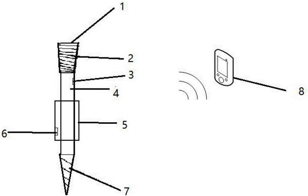
[0086] Attached below figure 1 The application principle of the present invention is further described. The orthopedic locking screw includes: a nut 1, a steel plate locking thread 2, a force sensor 3, a screw rod 4, a jacket 5, a deformation sensor 6, a cortical bone thread part 7, and an intelligent terminal 8.

[0087] The intelligent terminal 8 is wirelessly connected with the force sensor 3 and the deformation sensor 6; the top of the locking screw is provided with a nut 1, the steel plate locking thread 2 on the side wall of the nut 1, the screw 4 is connected to the nut 1, and the side wall of the screw 4 is provide...


PUM


Abstract

The invention discloses an orthopedic locking screw. The orthopedic locking screw comprises an intelligent terminal which is wirelessly connected with a force sensor and a deformation sensor; the top end of locking screw is provided with a nut, the side wall of the nut is provided with a steel plate locking thread, a screw rod is connected with the nut, the side wall of the screw rod is provided with the force sensor and a clamp sleeve, the outer side wall of the clamp sleeve is provided with a deformation sensor, and the bottom end of the screw rod is provided with a cortical bone thread part; the nut is a screw head and is a locking screw head provided with double-headed taper threads; the upper end of the screw rod is provided with a steel plate locking thread, and the bottom of the screw rod is provided with a cortical bone thread. The orthopedic locking screw is beneficial for promoting bones to achieve circumferential healing and promoting circumferential growth of bone callus, force and deformation amount of bone joints can be displayed, and therefore people can precisely analyze and research the biomechanical property and kinematics characteristics of the bone joints so as to establish a guidance theory of orthopedic therapies.

Description

technical field [0001] The invention belongs to the technical field of orthopedic medical devices, in particular to an orthopedic locking screw. Background technique [0002] The plate and screw system is one of the main means to treat fractures. Since the bone plate has been used for fracture treatment, it has a history of one hundred years so far. In the early 1960s, many scholars summed up the previous methods of fixing fractures with plate compression, and proposed four principles for treating fractures, namely: anatomical reduction of fracture fragments, strong internal fixation of each fracture fragment, and protection of blood supply at the end of the fracture. , Early mobilization of joints reduces fracture complications. [0003] However, after a long period of clinical follow-up and experiments, it was found that the stress shielding effect of hard plate fixation reduced the normal physiological stress stimulation of the bone, resulting in resorption of the cortic...

Claims


Application Information

Patent Timeline
IPC IPC(8): A61B17/68A61B17/86
CPCA61B17/683A61B17/8605A61B17/8625A61B2017/564
Inventor 张立沼李永孙增丽
Owner 张立沼
Learn More