
Fixed wing aircraft

An aircraft model and fixed-wing technology, applied in the field of aviation model, can solve the problems of affecting the streamline of the fuselage, increasing the load of the aircraft model, affecting the adjustment of the flight power of the flight attitude, etc., and achieves the effect of precise switching and accurate adjustment of the flight attitude.

Inactive Publication Date: 2016-11-23
叶灵
View PDF10 Cites 0 Cited by
  • Summary
  • Abstract
  • Description
  • Claims
  • Application Information

AI Technical Summary

Problems solved by technology

[0002] At present, the flight attitude adjustment of the aviation model mainly depends on the airflow pressure difference between the two sides of the wings. Usually, the methods of using the two sides of the wings to control the flight include: using the mechanical structure to change the tilt angle of the two sides of the wings or using the Vertical fans are installed on the wings to adjust the inclination angle of the wings on both sides; this method is not convenient for precise vector control of the aircraft model, and the movable wings are not strong enough. The strength has higher requirements. On the other hand, the installation of vertical fans on both sides of the wings not only increases the load of the aircraft model, but also the exposed vertical fans affect the streamline of the fuselage, which in turn affects the flight dynamics and the adjustment of the flight posture. The powerful power required for the vertical take-off and landing of the aircraft model needs to be equipped with more power engines, and the vertical engine is turned off during level flight, which becomes a burden on the aircraft model

Method used


Image

  • Fixed wing aircraft
  • Fixed wing aircraft
  • Fixed wing aircraft

Examples


Embodiment Construction

[0021] The present invention will be further described below in conjunction with accompanying drawing and specific embodiment:

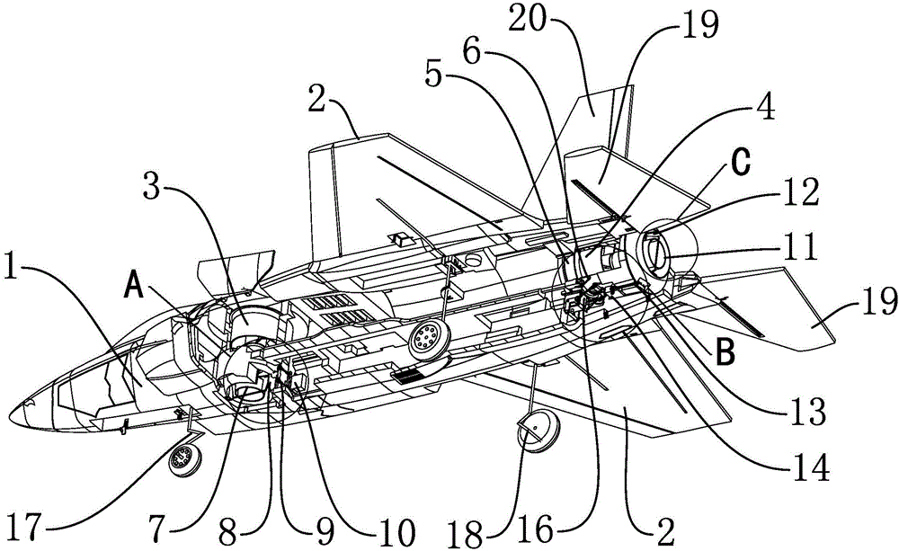
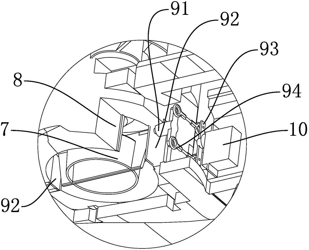
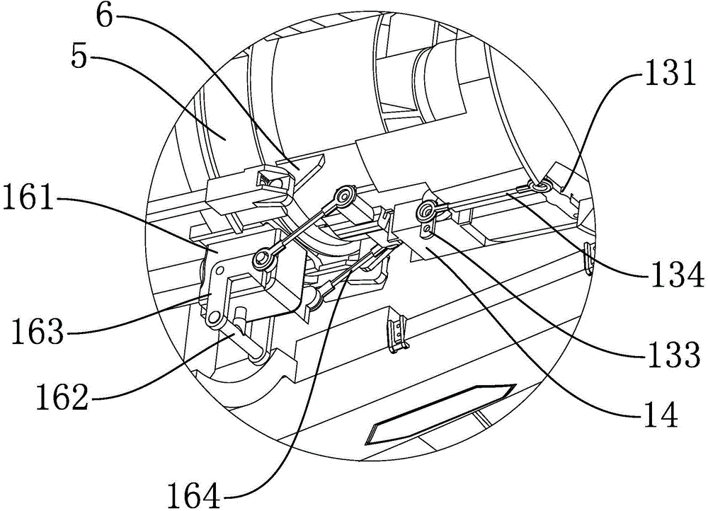
[0022] refer to figure 1 As shown, the fixed-wing aircraft model disclosed by the present invention includes a fuselage 1 and fixed wings 2 fixed on both sides of the fuselage 1, and the fixed-wing aircraft model also includes a front ducted power group 3 and a rear ducted power group 4, The front ducted power group 3 is vertically arranged in the middle of the fuselage 1, and the airflow generated by the front ducted power group 3 is directed towards the lower surface of the fuselage 1. This arrangement effectively utilizes a ducted power group to realize flight in the horizontal direction. It is stable and does not affect the streamline of the fuselage 1 at the same time. The rear duct power group 4 is connected to the rear part of the fuselage 1 through the rear duct fixing seat 5, and the rear duct power group 4 rotates around the fuselage throu...


PUM


Abstract

The invention discloses a fixed wing aircraft model. The fixed wing aircraft model comprises an aircraft body, fixed wings fixed on the two sides of the aircraft body and a front duct power unit and a back duct power unit, wherein the front duct power unit is vertically arranged in the middle of the aircraft body, air flow generated by the front duct power unit faces the lower surface of the aircraft body, the back duct power unit is connected to the tail of the aircraft body through a back duct fixing seat, and different angles are formed between the back duct power unit and the aircraft body through rotation of a back duct rotating seat around the aircraft body. According to the fixed wing aircraft model convenient for vector control over flight forms, vertical take-off and landing are achieved, level flight can be achieved through the fixed wings, a precise vector control mechanism is arranged, and the flight modes are stably and quickly switched.

Description

【Technical field】 [0001] The invention relates to an aviation model, in particular to a fixed-wing aircraft model. 【Background technique】 [0002] At present, the flight attitude adjustment of the aviation model mainly depends on the airflow pressure difference between the two sides of the wings. Usually, the methods of using the two sides of the wings to control the flight include: using the mechanical structure to change the tilt angle of the two sides of the wings or using the Vertical fans are installed on the wings to adjust the inclination angle of the wings on both sides; this method is not convenient for precise vector control of the aircraft model, and the movable wings are not strong enough. The strength has higher requirements. On the other hand, the installation of vertical fans on both sides of the wings not only increases the load of the aircraft model, but also the exposed vertical fans affect the streamline of the fuselage, which in turn affects the flight dy...

Claims


Application Information

Patent Timeline
IPC IPC(8): A63H27/18A63H27/22
Inventor 叶灵
Owner 叶灵
Learn More