riveting device

A riveting device and screwing technology, which is applied in the field of riveting devices, can solve the problem that hexagon socket head cap screws cannot be used, etc.

Active Publication Date: 2018-05-11
刘保坊
View PDF6 Cites 0 Cited by
  • Summary
  • Abstract
  • Description
  • Claims
  • Application Information

AI Technical Summary

Problems solved by technology

If the special locking element 14 is not available, certain hexagon socket head screws cannot be used

Method used


Image

  • riveting device
  • riveting device
  • riveting device

Examples


Embodiment Construction

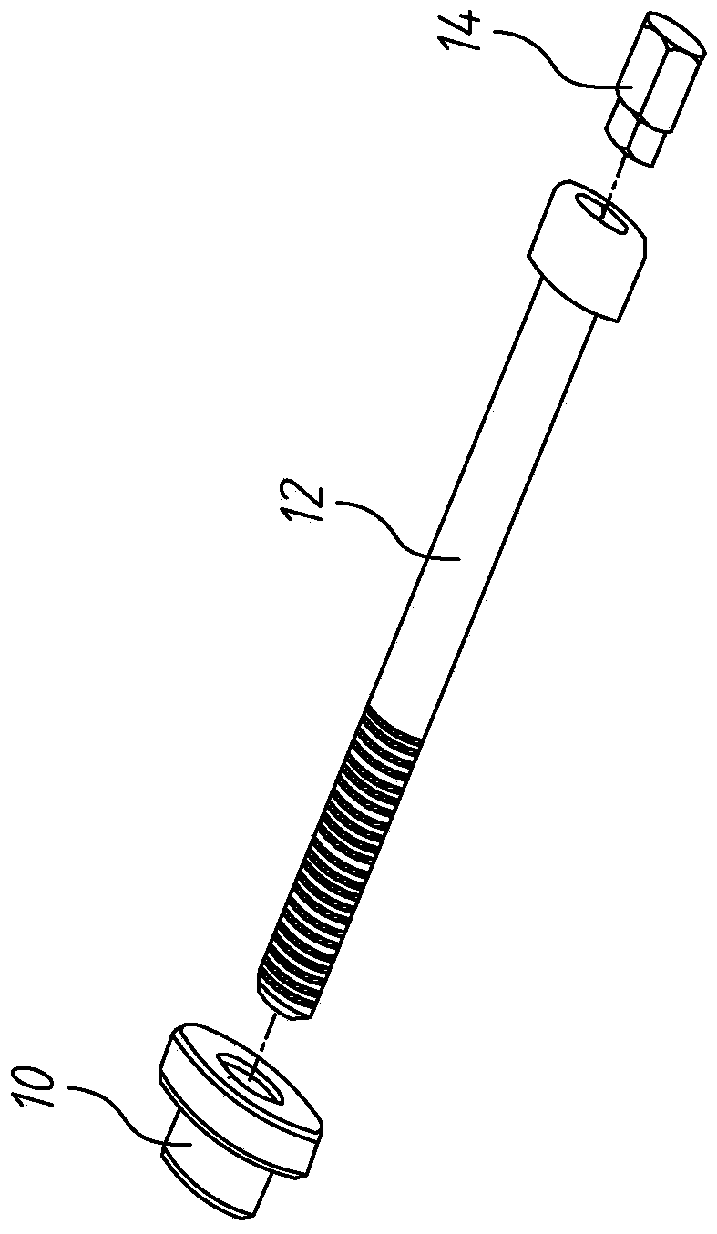
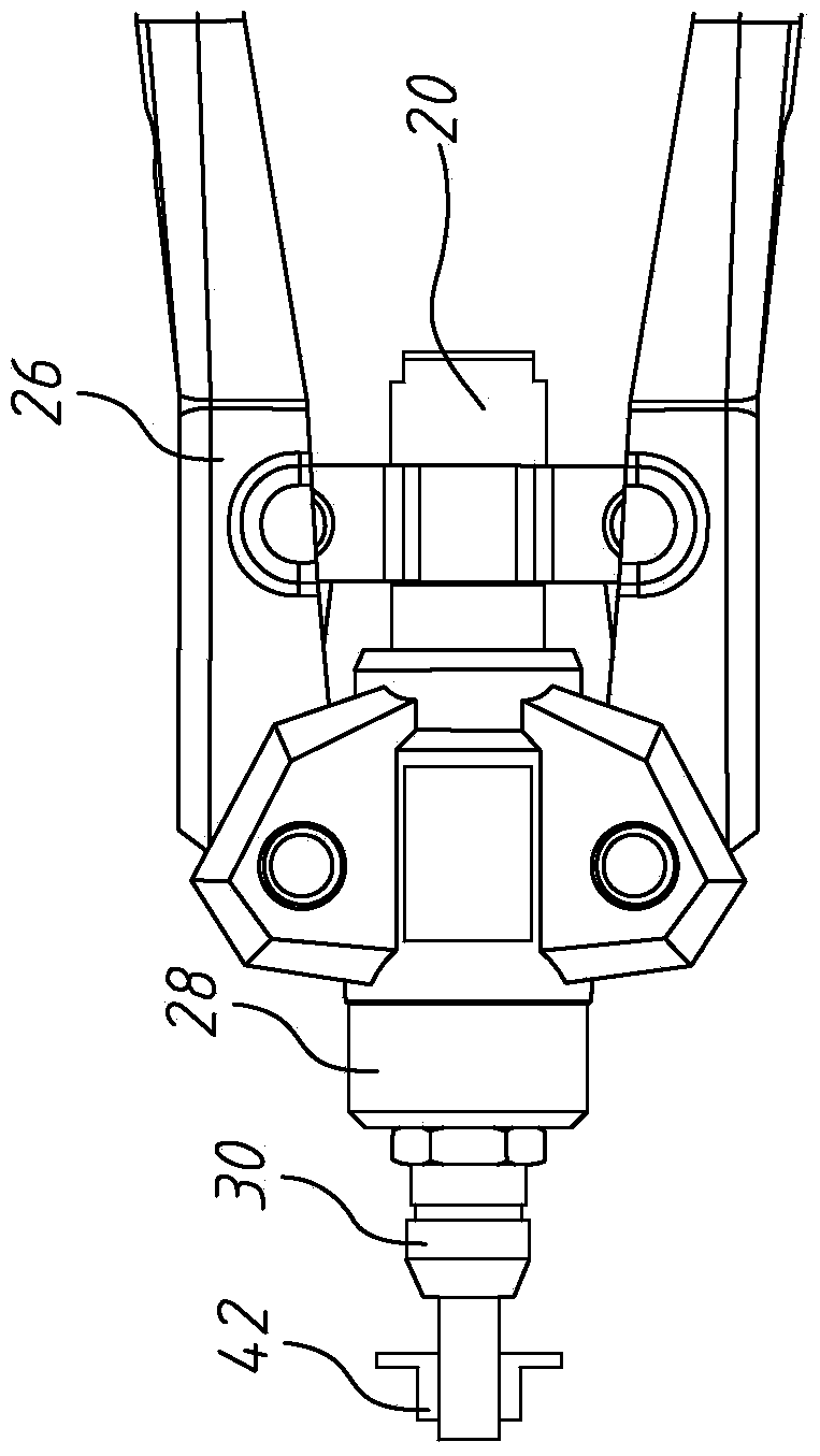
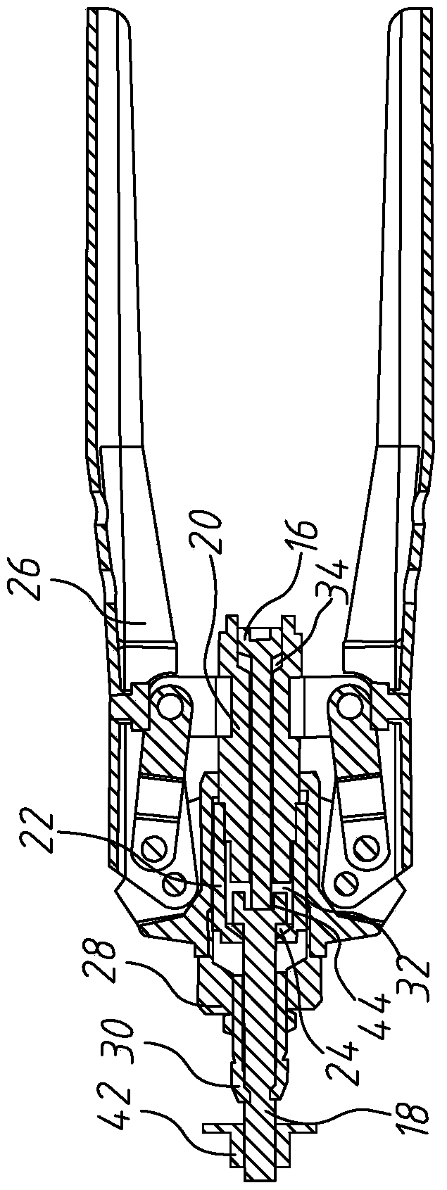
[0035] See figure 2 , image 3 , Figure 4 , Figure 5 , Image 6 versus Figure 7 The riveting device of the present invention includes a push rod 16, a screw 18, an inner guide sleeve 20, an outer guide sleeve 22, a buckle ring 24, a driver 26, an outer protective tube 28 and an inner protective tube 30, The push rod 16 is a metal push rod, and the screw 18 is a metal screw to serve as a tooth rod (MANDREL). The shape of the screw 18 is not limited. The inner guide sleeve 20 is a metal inner guide sleeve, and the outer guide sleeve 22 is a metal outer The guide sleeve and the clasp 24 are metal clasps. Here, the driver 26 takes a manual driver as an example, such as a manual handle, and is fixed in combination with the inner guide sleeve 20. The inner guide sleeve 20 has a first space 32 and a second space 34 communicating with each other, and the first space 32 surrounds a part of the second space 34. The side wall of the head of the push rod 16 has a first thread, and the...


PUM


Abstract

The invention discloses a riveting device, which includes an inner guide sleeve, an outer guide sleeve, a buckle ring and a driver. A push rod is inserted in the inner guide sleeve, the outer guide sleeve is set on the inner guide sleeve, the buckle is located in the outer guide sleeve, and is close to each other, the outer guide sleeve and the buckle are inserted by a screw, and the screw body of the screw It is exposed from the outer guide sleeve to be screwed with a pull cap, and the screw head of the screw is located in the inner guide sleeve and is close to between the buckle ring and the push rod. The driver is combined with the inner guide sleeve, so that the inner guide sleeve, the push rod, the outer guide sleeve, the buckle ring, the screw and the pull cap move synchronously on the driver to rivet the pull cap. The present invention uses a push rod, a buckle and an outer guide sleeve to fix the screw, so as to avoid being limited by the size or shape of the screw head of the screw.

Description

Technical field [0001] The invention relates to a riveting device, in particular to a riveting device that can use screws with any screw head. Background technique [0002] The current pull cap riveting tool needs to be matched with "MANDREL", and then the pull cap is locked on the tooth bar clockwise, and then the user uses the tool to make the tooth bar walk backwards to reach the riveting cap the goal of. After the riveting is completed, the pull cap will be fixed on the workpiece, and the tooth rod needs to be turned counterclockwise to separate the tooth rod and the pull cap. At present, the pull cap tools on the market all use special tooth sticks, which means that each manufacturer has its own tooth stick design. Because the tooth rod needs to match the thread specification of the pull cap, sometimes the tooth rod matched with the tool is not suitable for the pull cap on the user's hand. The most obvious example is that the user's tool is matched with a metric rod, but ...

Claims


Application Information

Patent Timeline
Patent Type & Authority Patents(China)
IPC IPC(8): B21J15/10
Inventor 刘保坊
Owner 刘保坊
Why Eureka
Try Eureka