Image formation device

a technology of image formation and transfer paper, which is applied in the direction of electrographic process, instruments, corona discharge, etc., can solve the problems of transfer paper shrinkage, and it normally takes 15 to 20 minutes for the original size of shrunken transfer paper to recover

Inactive Publication Date: 2005-07-21
CANON KK
View PDF2 Cites 22 Cited by
  • Summary
  • Abstract
  • Description
  • Claims
  • Application Information

AI Technical Summary

Benefits of technology

[0015] According to a first aspect of the present invention, an image formation device is provided. Such an image formation device performs an image formation process by generating a pulse signal corresponding to image data; turning on / off a laser beam emitted towards a photosensitive element based on the pulse signal so as to form an electrostatic latent image on the photosensitive element; developing the electrostatic latent image; transferring the latent image to transfer paper; and fixing the transferred image on the transfer paper. The image formation device includes an obtainer for obtaining shrinkage or expansion information of the transfer paper before or after the image is fixed onto the transfer paper; a changer for changing a scanning rate of the laser beam based on the shrinkage or expansion information obtained by the obtainer if the image formation process is to be performed again on the same paper already having the image fixed thereon; and a converter for changing a pulse width for each pixel of the image data based on the scanning rate changed by the changer when the pulse signal corresponding to the image data is generated.
[0016] According to a second aspect of the present invention, an image formation device is provided, which performs an image formation process by generating a pulse signal corresponding to image data; turning on / off a laser beam emitted towards a photosensitive element based on the pulse signal so as to form an electrostatic latent image on the photosensitive element; developing the electrostatic latent image; transferring the latent image to transfer paper; and fixing the transferred image on the transfer paper. The image formation device of the second aspect includes a changer for changing a scanning rate of the laser beam emitted towards the photosensitive element when the image formation process is to be performed on both faces of the same transfer paper such that a first latent-image formation process for a front face of the transfer paper and a second latent-image formation process for a back face of the transfer paper are to be performed at different scanning rates; and a converter for changing an intensity of the laser beam based on the scanning rate changed by the changer such that the intensity of the laser beam emitted towards the front face is different from the intensity of the laser beam emitted towards the back face.
[0017] According to these structures, even if the main-scanning rate is changed in order to prevent inconsistent sizes of formed images, such an image formation device can compensate for the difference in the density level of the subsequent image, which may be caused by the change in the main-scanning rate.
[0018] The above and other features, and advantages of the present invention will become more apparent from the following detailed description taken in conjunction with the accompanying drawings.

Problems solved by technology

However, when using such a thermal-fixing technique to fix the toner image on the transfer paper, the heat causes the moisture in the transfer paper to evaporate and thus causes the transfer paper to shrink.
Furthermore, it is generally known from experience that it normally takes about 15 to 20 minutes for the shrunken transfer paper to recover its original size.

Method used


Image

  • Image formation device
  • Image formation device
  • Image formation device

Examples


first embodiment

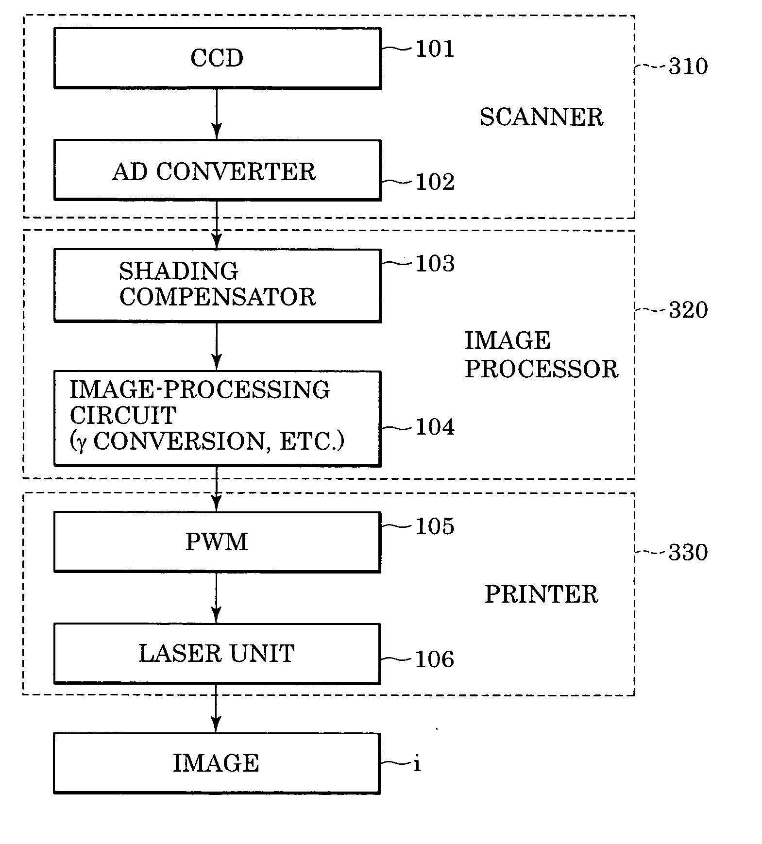
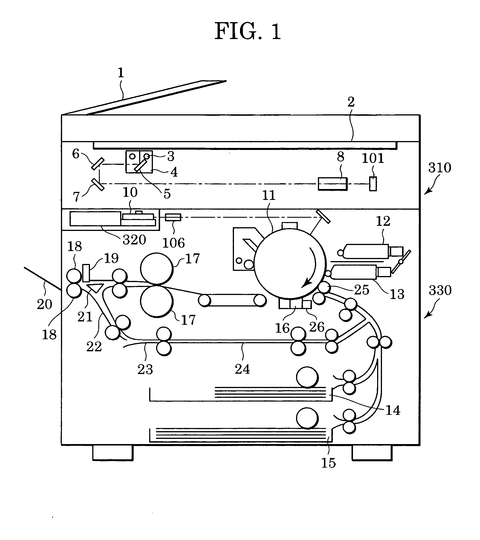
[0030]FIG. 1 is a cross-sectional view of an electro-photographic digital copier according to the present invention. Operation of the digital copier will also be described with reference to FIG. 3, which illustrates an image formation process from a photo-electric conversion step to a latent-image formation step performed by the digital copier.

[0031] Among other components, the digital copier according to the present embodiment includes a scanner 310 and a printer 330. The scanner 310 includes a document feeder 1 which feeds original documents disposed thereon one by one to a glass base 2. Moreover, the scanner 310 further includes a scanner unit 4 which contains a lamp 3 and a scanning mirror 5. While the lamp 3 is turned on, the scanner unit 4 is capable of moving back and forth in the horizontal direction in FIG. 1 so as to photoscan an image of each document disposed on the glass base 2. In this case, the light reflected from the document, i.e. image light, travels through scann...

second embodiment

[0063] To switch the rotational rate of the polygon motor 110, i.e. the main-scanning rate, in a multilevel manner, the number of PWM conversion tables T, i.e. the number of the rules, may be increased. Furthermore, for continuously performing double-sided recording or multilayer recording on multiple sheets of transfer paper of the same paper type, the shrinkage or expansion proportion calculated for the first sheet of transfer paper may be used for the second and additional transfer papers. This can reduce the workload on the CPU 117. This concept applies to the present invention, which will be described later.

[0064] According to the first embodiment, when image formation is to be performed multiple times on a sheet of transfer paper having an image fixed thereon, the rotational rate of the polygon motor 110, i.e. the main-scanning rate, is switched so as to prevent inconsistent sizes of the formed images due to shrinkage or expansion of the transfer paper. Moreover, an appropriat...

third embodiment

[0071] In other words, referring to FIG. 8, the CPU 117 in the main controller 116 sends an intensity compensation signal S409 to the laser driver 114 based on a shrinkage or expansion proportion of the transfer paper determined by the optical sensor 26. In this case, a PWM conversion table T in the PWM 105 is constant regardless of the main-scanning rate based on the shrinkage or expansion proportion of the transfer paper.

[0072]FIG. 9 illustrates the internal structure of the laser driver 114 and the laser unit 106. The laser unit 106 defining an optical scanner of laser beams includes a laser diode 404, and a photo-diode 405 disposed adjacent to the laser diode 404. Some components of a laser beam from the laser diode 404 are received by the photo-diode 405, and are amplified by a monitor amplifier 406. Thus, a signal S407 proportional to the intensity of the emitted laser beam is obtained. Subsequently, the signal S407 is compared with a laser-beam target-intensity standard sign...


PUM


Abstract

An image formation device changes the rotational rate of a polygon motor, i.e. the main-scanning rate, and selects one of pulse width conversion tables when an image formation is performed multiple times on a single sheet of transfer paper. The changing of the main-scanning rate is for preventing inconsistent sizes between a first recorded image and a second recorded image caused by shrinkage of transfer paper. The pulse width conversion tables allow the pulse widths to be modulated.

Description

BACKGROUND OF THE INVENTION [0001] 1. Field of the Invention [0002] The present invention relates generally to electro-photographic image formation methods and devices such as digital copiers and laser beam printers, and particularly, to an image formation method and device which generates a pulse signal based on image data so as to form an electrostatic latent image on a photosensitive element. [0003] 2. Description of the Related Art [0004] In a typical image formation device using an electro-photographic technique, a transferred toner image is fixed onto a sheet of transfer paper in order to form a permanent image on the paper. The toner image is usually fixed onto the transfer paper using thermal fixing. Various types of thermal-fixing techniques include hot air fixing, oven fixing, and more recently, heating roller fixing. In the heating-roller technique, a heating roller and a pressure roller are disposed in parallel to each other in the conveying path of the transfer paper, a...

Claims


Application Information

Patent Timeline
Patent Type & Authority Applications(United States)
IPC IPC(8): B41J2/44B65H7/06G03G15/00G03G15/01G03G15/04G03G15/043G03G21/00G03G21/14H04N1/113H04N1/12H04N1/23
CPCG03G15/043G03G2215/0404H04N1/1135G03G15/0435H04N1/40037H04N2201/04767H04N1/12
Inventor YAMADA, NAOTOKAJI, HAJIMEYAMAZAKI, YOSHITAKANOGUCHI, JUNICHIKAWAKAMI, TAKAYUKIMOTOYAMA, HAJIMEOGAWARA, SATOSHIOKA, YUSHIMORI, AKIHITO
Owner CANON KK
Why Eureka
Try Eureka