Device for achieving multi-hole tapping

A technology of installation position and tap, which is applied in the direction of tangent device, metal processing equipment, manufacturing tools, etc., can solve the problems of low production efficiency, limited test device, and position accuracy cannot be guaranteed accurately, so as to reduce the accumulation of semi-finished products, solve efficiency bottlenecks, Use a wide range of effects

Inactive Publication Date: 2016-11-23
SHANGHAI QIANGJING METAL PROD
View PDF10 Cites 0 Cited by
  • Summary
  • Abstract
  • Description
  • Claims
  • Application Information

AI Technical Summary

Problems solved by technology

[0002] At present, medium and large threaded holes can be processed by turning or milling. Small and medium threaded holes are mainly tapped by fitters manually. Manual processing methods are difficult to improve in terms of quality stability, efficiency, and cost reduction of small tools. It is necessary to explore high efficiency and stability. processing method
[0003] The existing tapping device can only tap one hole at a time, and the production efficiency is too low. Moreover, in the engineering application of the step tapping technology, there are currently the following deficiencies: the application of the step tapping technology is mostly limited to the test device at present. There is no stable product suitable for engineering applications; the equipment carrier of the stepping thread tapping device is generally an ordinary drilling machine, which can solve the processing problem of a single threaded hole, but for the processing of grouped threaded holes with high positional accuracy, the positional accuracy cannot be accurately guaranteed
[0004] Chinese patent CN104070362A discloses a casing punching and tapping device, which includes a horizontally arranged workbench, a base for placing the casing on the workbench that can move linearly and reciprocatingly, and a base that is arranged in sequence along the moving direction of the base. Punching assembly and tapping assembly, the punching assembly can punch holes on the left side, right side and bottom surface of the casing at the same time, and the tapping assembly can simultaneously punch holes on the left side, right side and bottom surface of the casing Tapping, the device still can not achieve multi-hole tapping

Method used


Image

  • Device for achieving multi-hole tapping

Examples


Embodiment

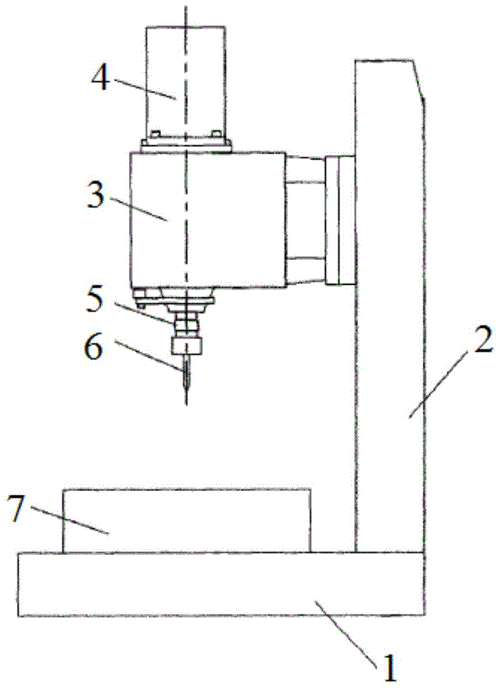
[0020] A device for realizing multi-hole tapping, its structure is as follows figure 1 As shown, it includes a base 1, a bracket 2 connected to the base 1, a main shaft 3 that moves up and down along the bracket 2, a servo motor 4 that controls the movement of the main shaft 3, the servo motor 4 changes speed through a pulley, and a tap connected under the main shaft 3 6. The center of the base 1 is also provided with a boss 7 for placing parts to be processed. The difference from the prior art solution is that, on the one hand, a plurality of taps 6 are connected below the main shaft 3; Move left and right. Specifically, the universal joint 5 is a movable plate that can be nested with each other and can move left and right. The movable plate is provided with a chute and a positioning buckle, the sliding is realized through the chute, and the position of the movable plate is fixed by the positioning buckle. Each movable plate is connected with a screw tap 6, and the install...


PUM


Abstract

The invention relates to a device for achieving multi-hole tapping. The device comprises a base, a support connected to the base, a spindle vertically moving along the support, a servo motor controlling the spindle to move and screw taps connected to the position below the spindle. The multiple screw taps are connected with the position below the spindle. The screw taps are connected with the spindle through universal joints, and the universal joints control the left-right movement of the screw taps in the horizontal direction. Compared with the prior art, the device is suitable for machining stamping parts with various hole diameters and tapping distances through adjustment of the distance among the screw taps and the installing positions of the screw taps, the application range is wide, the one-time tapping number is large, and efficiency is high; and tapping treatment on the different parts is controlled by adjusting the left-right rotation angles of the spindle.

Description

technical field [0001] The invention relates to a tapping device, in particular to a device for realizing multi-hole tapping. Background technique [0002] At present, medium and large threaded holes can be processed by turning or milling. Small and medium threaded holes are mainly tapped by fitters manually. Manual processing methods are difficult to improve in terms of quality stability, efficiency, and cost reduction of small tools. It is necessary to explore high efficiency and stability. processing method. [0003] The existing tapping device can only tap one hole at a time, and the production efficiency is too low. Moreover, in the engineering application of the step tapping technology, there are currently the following deficiencies: the application of the step tapping technology is mostly limited to the test device at present. There is no stable product that meets engineering applications; the equipment carrier of the step-by-step tapping device is generally an ordin...

Claims


Application Information

Patent Timeline
Patent Type & Authority Applications(China)
IPC IPC(8): B23G1/20B23G1/44
Inventor 席晓峰
Owner SHANGHAI QIANGJING METAL PROD
Why Eureka
Try Eureka