
Circuit board rapid modification platform device

A platform device and circuit board technology, applied in auxiliary devices, printed circuits, soldering irons, etc., can solve problems such as affecting the progress and efficiency of circuit debugging, difficult to replace and reuse, and damage to the heating core of the electric soldering iron, so as to shorten the modification cycle. , The function is concentrated and specific, and the effect of easy replacement

Inactive Publication Date: 2018-04-13
HUANGHE S & T COLLEGE
View PDF6 Cites 0 Cited by
  • Summary
  • Abstract
  • Description
  • Claims
  • Application Information

AI Technical Summary

Problems solved by technology

Due to the variety of these instruments, the functions are not concentrated and not specific
Therefore, a lot of troubles are caused in the use process, which seriously affects the progress and efficiency of circuit debugging.
[0005] In addition, at present, when soldering circuit boards, traditional constant-temperature soldering irons are generally used, and electric soldering irons are generally used for hand-held operations. This welding method has the following technical defects: 1. Poor safety, easy to Injury to people or objects; 2. The operation is cumbersome and the welding efficiency is low; 3. Using an electric soldering iron for welding, because there is no suitable support and adjustment platform, the reliability of welding is poor; 4. The heating core of the electric soldering iron is damaged Afterwards, it is not easy to replace and reuse

Method used


Image

  • Circuit board rapid modification platform device
  • Circuit board rapid modification platform device
  • Circuit board rapid modification platform device

Examples


Embodiment Construction

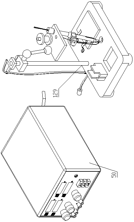
[0040] Such as Figure 1-Figure 8 As shown, the circuit board rapid modification platform device of the present invention includes a control host 50 and a circuit board rapid soldering device 129 .

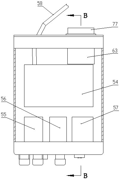
[0041] The control host 50 includes a box body 53 in the shape of a cuboid. The box body 53 is provided with a power drive module 54, a switching power supply control module 55, a load control module 56 and a welder constant temperature heating module 57. The rear side of the power drive module 54 is connected to a Stretch out the 220V power line 58 of box body 53 behind, the inner rear part of box body 53 is provided with the radiator 63 that contacts with power drive module 54; Load control module 56 is connected with power drive module 54, and load control module 56 is connected with switch respectively. The power supply control module 55 is connected with the welder constant temperature heating module 57.

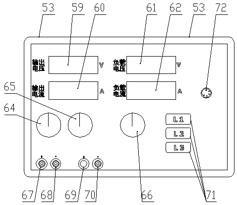
[0042] The front panel of the cabinet 53 is provided with an output v...


PUM


Abstract

The invention discloses a quick modification platform device of a circuit board. The device comprises a quicker circuit board welder, and a control host machine for supplying electricity to the quick circuit board welder; the quick circuit board welder includes a base; a support guide rod is arranged on the back side of the middle part of the upper surface of the base; a slide block is slidingly inserted in the support guide rod; the side part of the slide block is in threaded connection with a positioning bolt ejected and matched with the support guide rod; a horizontal rod is arranged on the front side of the slide block; the front end of the horizontal rod is connected with a connecting rod through an upper ball hinge; the lower end of the connecting rod is connected with a mounting platform through a lower ball hinge; a fixed shaft is vertically arranged on the upper surface of the mounting platform; a silk winding frame is rotationally arranged on the fixed shaft; a silk through hole and a mounting hole are formed in the mounting platform; an electric soldering iron module is inserted in the mounting hole; and the base is provided with two placing groove holes for limiting the lower end of the electric soldering iron module. The quick modification platform device of the circuit board is high in welding efficiency of the circuit board, high in safety and reliability, excellent in welding quality and convenient for replacing such wearable parts as ceramic heating cores.

Description

technical field [0001] The invention belongs to the technical field of electronic circuits, in particular to a platform device for quickly modifying circuit boards. Background technique [0002] The signal changes and functions of electronic circuits have certain abstract characteristics, and it is difficult to know the working status and characteristics of the circuit through direct observation. Therefore, in the application development and design of electronic products and equipment, a large number of instruments and equipment are needed to build a test environment and obtain circuit status. [0003] Circuit debugging refers to the process of verifying whether the expected performance target is achieved at different stages in the circuit development process, finding the reason for the problems that arise, and repeatedly modifying and verifying the process. [0004] There are many kinds of commonly used circuit debugging instruments, including adjustable regulated power su...

Claims


Application Information

Patent Timeline
Patent Type & Authority Patents(China)
IPC IPC(8): B23K3/03B23K3/08B23K101/42
CPCB23K3/03B23K3/08
Inventor 刘扬徐彬郑观升
Owner HUANGHE S & T COLLEGE
Learn More