
Oil pump gear shaft spiral flow type barrel finishing jig device and method

A swirl type, gear shaft technology, applied in the direction of grinding drive device, grinding workpiece support, metal processing equipment, etc., can solve the problems of low processing efficiency of tooling, poor processing effect of gear end face, etc., achieve strong adaptability, improve The effect of skin finishing and the effect of improving the efficiency of skin finishing

Active Publication Date: 2016-11-23
LANGFANG NORTH TIANYU ELECTROMECHANICAL TECH
View PDF10 Cites 10 Cited by
  • Summary
  • Abstract
  • Description
  • Claims
  • Application Information

AI Technical Summary

Problems solved by technology

[0004] Based on the main defects of the above-mentioned prior art, the present invention proposes a circular array multi-station oil pump gear shaft tooling structure that adopts the rotary motion of the main shaft of the swirl-type barreling finishing equipment to synchronously drive and reciprocate in the vertical direction. It is to solve the problems of low processing efficiency of existing tooling and poor processing effect of gear end face

Method used


Image

  • Oil pump gear shaft spiral flow type barrel finishing jig device and method
  • Oil pump gear shaft spiral flow type barrel finishing jig device and method
  • Oil pump gear shaft spiral flow type barrel finishing jig device and method

Examples


Embodiment Construction

[0027] The present invention will be described in detail below in conjunction with specific embodiments.

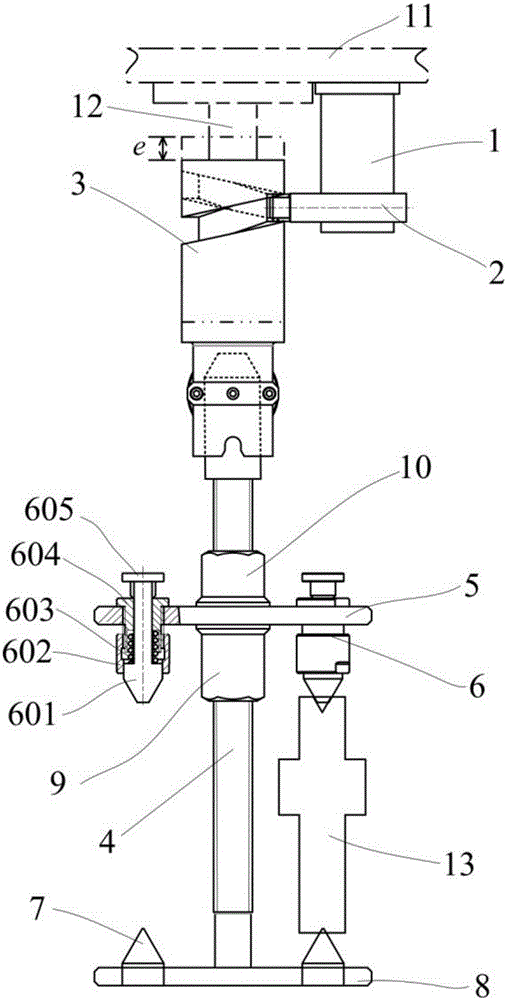
[0028] Such as figure 1 As shown in the figure, a swirl-flow barrel finishing tooling device for an oil pump gear shaft includes a cam mechanism and a circular array tooling body. The cam mechanism includes a pin seat 1, a rotary pin 2, a cylindrical cam 3, and one end of the rotary pin 2 is connected to The spiral groove around the circle of the cylindrical cam 3 is matched, and the other end is fixed with the pin seat 1. The cylindrical cam 3 is connected with the main shaft 12 of the finishing machine by a movable spline, and the pin seat 1 is connected with the finishing machine. Machine headstock 11 is fixedly connected. According to the basic working principle of the cam and the composition of the cam mechanism, it can be seen that when the main shaft 12 of the skin finishing machine rotates during work, the vertical direction of the rotary pin 2 is The movement i...


PUM


Abstract

The invention discloses an oil pump gear shaft spiral flow type barrel finishing jig device and method. The oil pump gear shaft spiral flow type barrel finishing jig device comprises a cam mechanism and a jig body. With the cam mechanism, it is achieved that the whole jig body can carry out perpendicular reciprocating motion additionally while carrying out rotation motion, and therefore, the effect of finishing carried out on the upper end face and the lower end face of a gear can be remarkably improved. The jig body comprises a jig shaft, an upper center disk, clamping adjustment mechanisms, lower centers and a lower center disk. More than one part can be clamped between the upper center disk and the lower center disk, and therefore, the production efficiency is high. Through two steps of adjustment, including coarse adjustment and fine adjustment, carried out on the distance between the upper center disk and the lower center disk, the parts can be controlled to rotate or not in the machining process, and the technological performance of finishing is greatly improved. After the oil pump gear shaft spiral flow type barrel finishing jig device is used for machining gear shafts, tooth surfaces, especially the upper end faces and the lower end faces of gears are good in machining effect.

Description

technical field [0001] The invention belongs to the field of finishing of free grinding tools. Specifically, the utility model relates to a tooling device capable of multi-station clamping and synchronous additional vertical reciprocating motion of parts and a method for using the device to perform swirl-type tumbling finishing. Background technique [0002] Swirl-type barrel finishing is a free abrasive finishing method, which is widely used in surface deburring and roughness reduction of small and medium-sized short shafts, camshafts, crankshafts and gear shafts. processing. Invention patent ZL92100312.9 "swirling flow high-precision polishing processing equipment and technology" first proposed "the main shaft drives the workpiece to be inserted into the drum filled with grinding blocks, and the main shaft and the drum make rotary motions respectively and generally the two rotate in opposite directions" The basic principle and processing technology of this swirl-type fin...

Claims


Application Information

Patent Timeline
Patent Type & Authority Applications(China)
IPC IPC(8): B24B31/02B24B41/02B24B41/06B24B47/12
CPCB24B31/0212B24B31/0224B24B41/02B24B41/06B24B47/12
Inventor 杨胜强高云松段东明王进军姜豪增王良辰王鹏
Owner LANGFANG NORTH TIANYU ELECTROMECHANICAL TECH
Learn More