
Combination type metal die protecting frame

A metal mold and combined technology, applied in the direction of manufacturing tools, tool storage devices, etc., can solve the problems of inability to disassemble, mold rack placement and handling restrictions, mold racks cannot be placed, etc., to achieve strong versatility and high efficiency. The effect of practical value

Inactive Publication Date: 2016-11-23
天津三兆金属制品有限公司
View PDF0 Cites 1 Cited by
  • Summary
  • Abstract
  • Description
  • Claims
  • Application Information

AI Technical Summary

Problems solved by technology

[0002] Molds are very important parts in industrial production, so molds need to be stored safely when not in use. Since many molds have requirements for precision, in order to prevent deformation, they generally cannot be stacked and placed directly, but placed on mold racks. Existing Mold racks are generally placed directly in the form of bookshelves in multiple layers. Due to the fixed structure of the mold racks, the placement and transportation of the mold racks are greatly restricted, especially the large mold racks cannot be placed in a small room, let alone used separately. , and for some metal molds, due to their high quality, ordinary mold frames cannot be placed a lot, wasting the upper space. If a new type of mold frame that can be combined freely can be invented, this kind of problem can be solved. We provide a combined metal mold guard

Method used

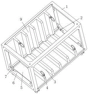
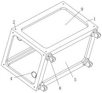
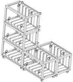

Image

  • Combination type metal die protecting frame
  • Combination type metal die protecting frame
  • Combination type metal die protecting frame

Examples


Embodiment Construction

[0013] The following will clearly and completely describe the technical solutions in the embodiments of the present invention with reference to the accompanying drawings in the embodiments of the present invention. Obviously, the described embodiments are only some, not all, embodiments of the present invention. Based on the embodiments of the present invention, all other embodiments obtained by persons of ordinary skill in the art without making creative efforts belong to the protection scope of the present invention.

[0014] see Figure 1-3 , the present invention provides a technical solution:

[0015] A combined metal mold cage, comprising a support frame 1, the joints in the support frame 1 are provided with mutually matching screw holes 2, and the support frame 1 is provided with a clamping hole 2 corresponding to each screw hole 2. Tighten the draw-in slot of the nut, the lower end of the support frame 1 is equipped with a universal wheel 8, and the support frame 1 is...


PUM


Abstract

The invention discloses a combination type metal die protecting frame. The combination type metal die protecting frame comprises a support frame, wherein screw joint holes matched with each other are formed in all connecting parts in the support frame, and the support frame is provided with clamping grooves used for clamping nuts at all parts corresponding to the screw joint holes; and universal wheels are mounted at the lower end of the support frame. According to the device, by designing a die protecting frame capable of being freely spliced and combined, placing plates can be changed according to the sizes of dies, or bigger die frames can be spliced according to the placing requirements of the dies and the sizes of rooms; in particular, for dies with large mass, a plurality of die frames can be directly placed on the ground after being disassembled, so that the deformation risk of the die frames, caused by the placing of the too many large-mass dies on the same die frame for a too-large height is avoided; and therefore, the device is strong in universality and high in practical value.

Description

technical field [0001] The invention relates to the field of combined mold guards, in particular to a combined metal mold guard. Background technique [0002] Molds are very important parts in industrial production, so molds need to be stored safely when not in use. Since many molds have requirements for precision, in order to prevent deformation, they generally cannot be stacked and placed directly, but placed on mold racks. Existing Mold racks are generally placed directly in the form of bookshelves in multiple layers. Due to the fixed structure of the mold racks, the placement and transportation of the mold racks are greatly restricted, especially the large mold racks cannot be placed in a small room, and cannot be disassembled. , and for some metal molds, due to their high quality, ordinary mold frames cannot be placed a lot, wasting the upper space. If a new type of mold frame that can be combined freely can be invented, this kind of problem can be solved. We offer a c...

Claims


Application Information

Patent Timeline
Patent Type & Authority Applications(China)
IPC IPC(8): B25H3/04
CPCB25H3/04
Inventor 郭嘉
Owner 天津三兆金属制品有限公司
Learn More