Air energy heat pump outdoor unit facilitating rapid heat dissipation and method

An air-energy heat pump and outdoor unit technology, applied in heat pumps, refrigerators, fluid heaters, etc., can solve the problems of no rapid heat dissipation, difficult air discharge, and difficult air discharge, so as to achieve high safety and avoid energy waste Effect

Active Publication Date: 2021-06-18
北京诺金伟业机电设备安装工程有限公司
View PDF7 Cites 0 Cited by
  • Summary
  • Abstract
  • Description
  • Claims
  • Application Information

AI Technical Summary

Problems solved by technology

[0003] Most of the existing outdoor units have a fan on one side of the refrigerant heat exchange tube, and the fan rotates to blow the air into the outdoor unit and contact the refrigerant heat exchange tube, so that the air contacts the refrigerant heat exchange tube and transfers the heat in the air to the refrigerant heat exchange tube. In the refrigerant in the refrigerant heat exchange tube, the outdoor unit is used as a heat exchanger to absorb heat from the outdoor air, but it is difficult to discharge the air after absorbing heat, and the air after absorbing heat is not easy to discharge, and the air fluidity in the outdoor unit is poor, resulting in the efficiency of heat exchange Low, and the fan blades are large in size, and the noise is high during high-speed rotation; in the process of using in hot weather, the outdoor unit acts as a heat exchanger to absorb heat from the outdoor air, and the air source heat pump has a high workload, but the current There is technology and there is no suitable technical method for rapid heat dissipation

Method used


Image

  • Air energy heat pump outdoor unit facilitating rapid heat dissipation and method
  • Air energy heat pump outdoor unit facilitating rapid heat dissipation and method
  • Air energy heat pump outdoor unit facilitating rapid heat dissipation and method

Examples


Embodiment 1

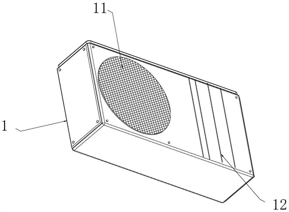
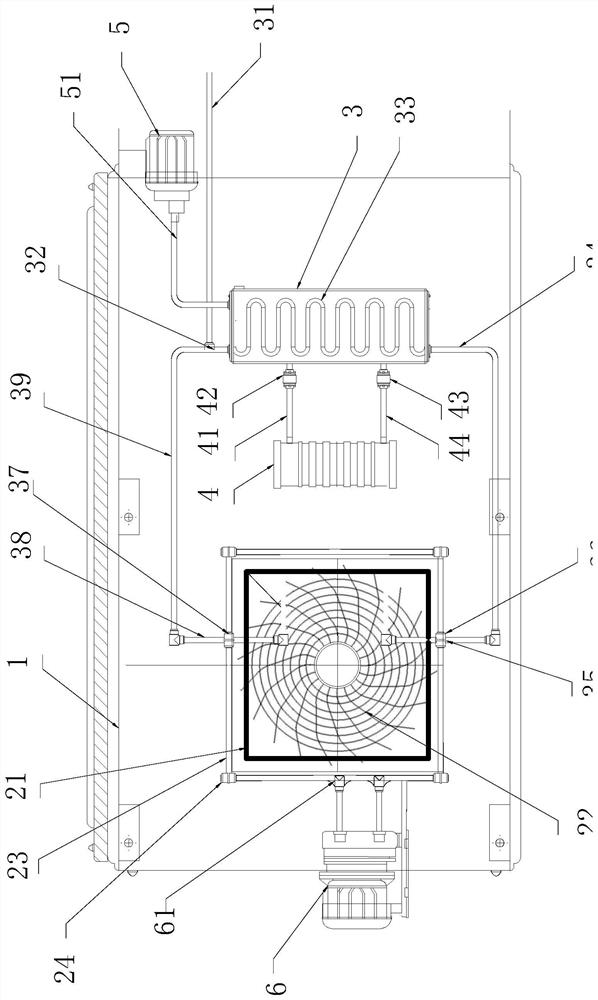
[0032] see figure 1 and image 3 , an air source heat pump outdoor unit that facilitates rapid heat dissipation, comprising a chassis 1, the chassis 1 is built with a heat pump installation area 11 and a cooling area 12, the heat pump installation area 11 is built with a thermal contact plate 21, and the thermal contact plate 21 is provided with an annular heat conducting frame 22, the edge of the thermal contact plate 21 is provided with an annular conduit 23, and the circular conduit 23 is provided with a circulation pump 24, and the cooling zone 12 is respectively provided with a low-pressure chamber 3 and a high-pressure chamber 4 , the cooling zone 12 is externally connected to a cooling water pipeline 31, the water delivery end of the cooling water pipeline 31 is provided with a three-way switch valve 32, and the low-pressure chamber 3 is built with a heat energy medium pipe 33, and the heat energy medium pipe 33 is in the shape of "S "Curve bending and folding design, ...

Embodiment 2

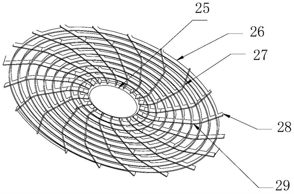
[0037] see image 3 , this embodiment is a further optimization of Embodiment 1. On the basis of it, a heat pump heat conduction substrate 25 is arranged in the middle of the annular heat conduction frame 22, and an annular outer diffusion frame 26 and a vertical The staggered frame 27 , the bottom of the annular outer diffusion frame 26 is provided with a thermal pad 29 fixed to the thermal contact plate 21 , and the vertical staggered frame 27 is in contact with the annular conduit 23 through the outer heat conduction sheet 28 . The heat pump heat conduction substrate 25, the annular outer diffusion frame 26 and the vertical interlaced frame 27 are all made of good heat conduction metal. The outer edge heat conducting sheet 28 is wound on the annular conduit 23 with a soft metal strip.

[0038] For the annular heat conduction frame 22, the heat pump heat conduction substrate 25 of this application is designed to perform close heat conduction with the heat pump, and then spr...

Embodiment 3

[0040] see figure 2 , this embodiment is a further optimization of Embodiment 1. On the basis of it, the other side of the thermal contact plate 21 is provided with a secondary cooling pump 6, and the secondary cooling pump 6 passes through the drainage branch pipe 61 and the annular conduit 23 connected. The annular conduit 23 forms a circulation loop with the secondary cooling pump 6 through the drainage branch pipe 61, which is used to reduce the temperature of the cooling water and play an auxiliary cooling effect.


PUM


Abstract

The invention relates to the technical field of air energy heat pump outdoor units, in particular to an air energy heat pump outdoor unit facilitating rapid heat dissipation and a method. The air energy heat pump outdoor unit comprises a case, and a heat pump mounting area and a cooling area are arranged in the case; a thermal contact plate is arranged in the heat pump mounting area, an annular heat conduction frame is arranged on the thermal contact plate, and an annular guide pipe is arranged on the edge of the thermal contact plate; a low-pressure cavity and a high-pressure cavity are formed in the cooling area, the cooling area is externally connected with a cooling water pipeline, the water conveying end of the cooling water pipeline is provided with a three-way change-over valve, a heat energy medium pipe is arranged in the low-pressure cavity, the heat energy medium pipe extends outwards to be connected with a water conveying pipeline, the water conveying pipeline is provided with a cooling water inlet pipe which is connected with the annular guide pipe through an input pump, and an output pump is arranged on the other side of the annular guide pipe and is externally connected with a backflow pipeline. Two relative space environments of the low-pressure cavity and the high-pressure cavity are designed in the outer case, and medium liquid is converted between the high-pressure environment and the low-pressure environment, so that a solution is vaporized, and heat is absorbed.

Description

technical field [0001] The invention relates to the technical field of an air energy heat pump outdoor unit, in particular to an air energy heat pump outdoor unit and a method for facilitating rapid heat dissipation. Background technique [0002] The air source water heater works according to the "reverse Carnot" principle. Specifically, the "outdoor unit" acts as a heat exchanger to absorb heat from the outdoor air, heat the low-boiling point working medium (refrigerant) and evaporate it, and the refrigerant vapor is compressed. The machine compresses and heats up and enters the water tank, releases heat to the water in it and condenses and liquefies, then throttles down and lowers the temperature and returns to the outdoor heat exchanger to enter the next cycle. [0003] Most of the existing outdoor units have a fan on one side of the refrigerant heat exchange tube, and the fan rotates to blow the air into the outdoor unit and contact the refrigerant heat exchange tube, so...

Claims


Application Information

Patent Timeline
Patent Type & Authority Applications(China)
IPC IPC(8): F24H4/02F24H9/00F25B30/06
CPCF24H4/02F24H9/0005F25B30/06
Inventor 庄小芳
Owner 北京诺金伟业机电设备安装工程有限公司
Why Eureka
Try Eureka