
A portable hip assist mechanism

A technology of power-assisted mechanism and hip joint, which is applied in manipulators, program-controlled manipulators, manufacturing tools, etc. It can solve the problems of low control accuracy, troublesome wearing, and high price, and achieve accurate control accuracy, good portability, and easy control. Effect

Inactive Publication Date: 2018-06-26
JIANGSU UNIV
View PDF5 Cites 0 Cited by
  • Summary
  • Abstract
  • Description
  • Claims
  • Application Information

AI Technical Summary

Problems solved by technology

[0003] The hip joint assist mechanism mainly adopts motor drive, hydraulic drive or pneumatic drive. At present, many hip joint assist mechanisms adopt hydraulic or pneumatic drive, but the hydraulic or pneumatic drive has the disadvantages of large noise, more pollution, short stroke, and low control accuracy. , making the structure of the hip joint assisting mechanism complex, bulky, troublesome to wear, and poor in coupling performance with the human body. In addition, most of the existing assisting exoskeletons on the market are complex in design and control and expensive, so there is an urgent need for a simple structure, convenient control, wearable A hip assist mechanism that is comfortable and conforms to the level of mass consumption

Method used


Image

  • A portable hip assist mechanism
  • A portable hip assist mechanism
  • A portable hip assist mechanism

Examples


Embodiment Construction

[0028] The following will clearly and completely describe the technical solutions in the embodiments of the present invention with reference to the accompanying drawings in the embodiments of the present invention. Obviously, the described embodiments are only some of the embodiments of the present invention, not all of them. Based on the embodiments of the present invention, all other embodiments obtained by persons of ordinary skill in the art without making creative efforts belong to the protection scope of the present invention.

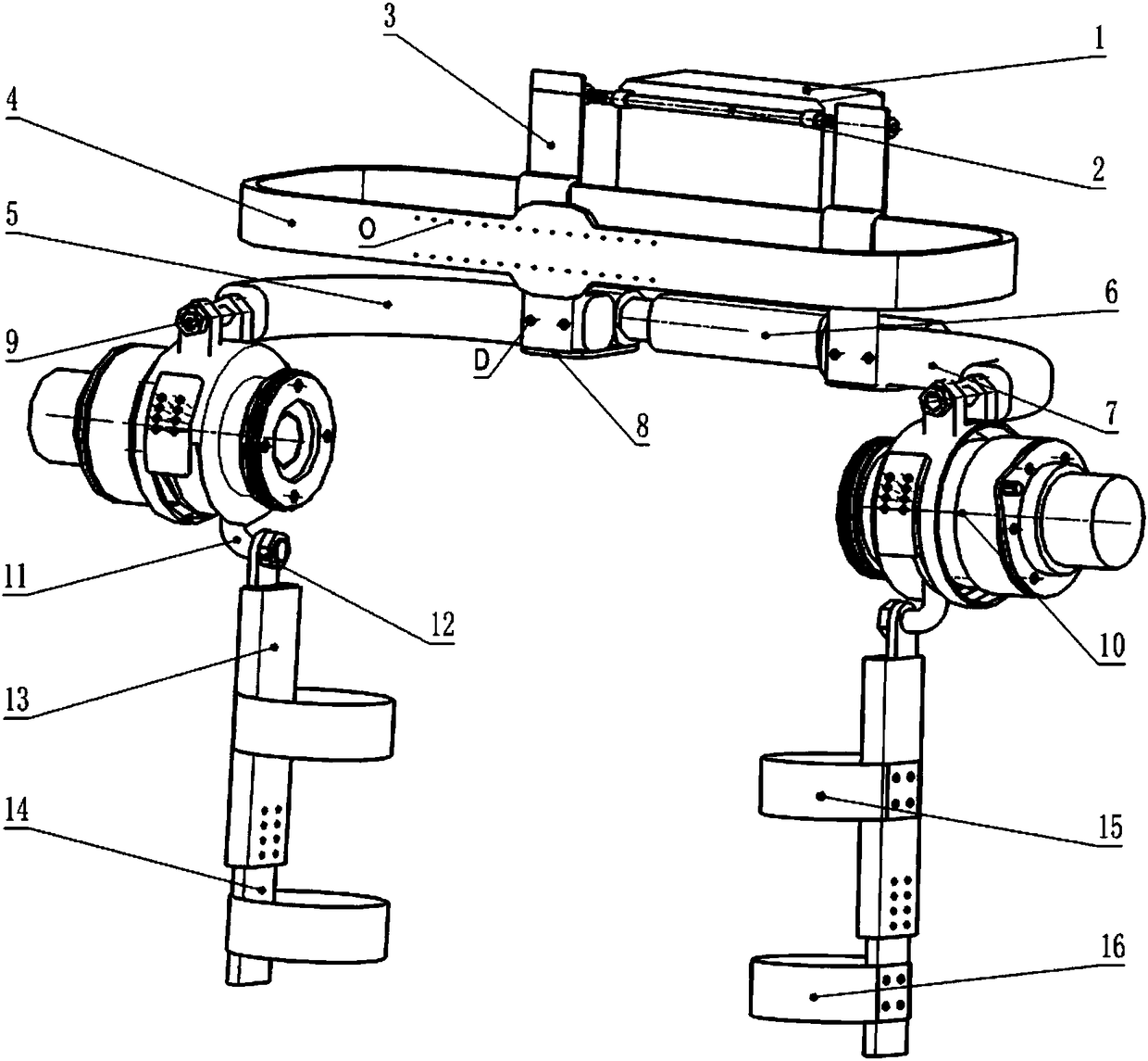
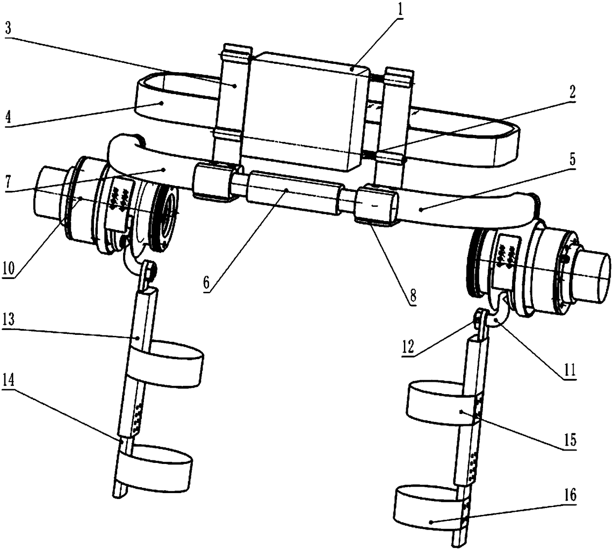
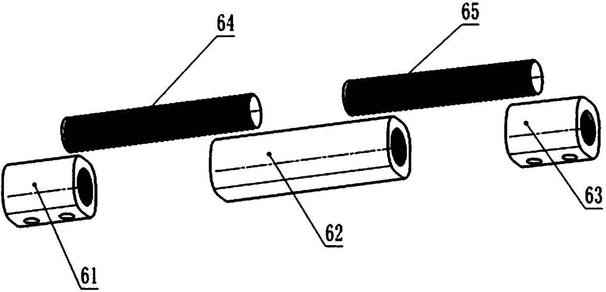
[0029] A portable hip joint assisting mechanism, comprising a control box 1, a support connecting rod 2, a back support plate 3, a belt 4, a right waist support 5, a waist adjustment mechanism 6, a left waist support 7, a hip joint driving mechanism 10, a connecting Part 11, the first thigh link 13 and the second thigh link 14;

[0030] The left waist support 7 and the right waist support 5 have the same structure and are L-shaped structures; the...


PUM


Abstract

The invention provides a portable hip joint assisting mechanism. A left waist support and a right waist support are the same in structure, i.e., both of an L-shaped structure. One ends of the left waist support and the right waist support are fixedly connected to two sides of a waist adjusting mechanism by means of connecting flanges. Two back support plates are fastened and connected to side surfaces of the left waist support and the right waist support by means of screws, and both perpendicular to the waist supports. Two support connecting rods arranged in parallel up and down are in threaded connection with the back support plates. A control box is suspended to the support connecting rods. A waist belt passes through sleeve holes in the middle portions of the back support plates. Hip driving mechanisms are located at lower sides of the waist supports and in threaded connection with the other ends of the left waist support and the right waist support by means of connecting shafts. A joint execution mechanism is formed by a first thigh connecting rod, a second thigh connecting rod, a first thigh binding band and a second thigh binding band. The portable hip joint assisting mechanism provides a motor-driven hip joint assisting mechanism for providing extra torque with the requirements of simple structure, low weight, safety and controllability and high practical and economical values on the mechanism.

Description

technical field [0001] The invention relates to a lower limb assisting device, in particular to a portable hip joint assisting mechanism. Background technique [0002] As an important joint of the lower limbs of the human body, the hip joint supports the weight of the entire torso. It bears much greater physiological pressure than other joints. Its health directly affects people's daily activities, such as walking, running and jumping, etc., because In this way, the hip joints are under high load in daily life. Excessive fatigue or even damage to the hip joints will cause various lesions. The hip joints of the elderly will decline with age and muscle strength. The torque is not enough to meet the needs of normal movement, and the hip assist mechanism can apply a reasonable external torque to the hip joint of the elderly to make up for the lack of output torque of the elderly and assist their movement. [0003] The hip joint assist mechanism mainly adopts motor drive, hydrau...

Claims


Application Information

Patent Timeline
Patent Type & Authority Patents(China)
IPC IPC(8): B25J9/00
CPCB25J9/0006
Inventor 王霄陈树洋王富良刘会霞高坤张国策
Owner JIANGSU UNIV
Learn More