Automatic wire clamping and drawing device

A stretching device and wire clamping technology, applied in the field of new automatic auxiliary equipment, can solve the problems of large waste of manual operation time, large size error, low efficiency, etc. Effect

Active Publication Date: 2016-11-23
深圳市国信达科技股份有限公司
View PDF6 Cites 1 Cited by
  • Summary
  • Abstract
  • Description
  • Claims
  • Application Information

AI Technical Summary

Problems solved by technology

[0002] At present, the tail clips of the power cord are manually placed in a single line during molding and injection molding, and the single line is inserted into the mold line groove, and it is necessary to manually measure the size with a ruler to determine the molding position of the tail clip. This operation method has low efficiency and large dimensional errors. , Manual operation time waste and other defects

Method used


Image

  • Automatic wire clamping and drawing device
  • Automatic wire clamping and drawing device

Examples


Embodiment Construction

[0021] Below with reference to accompanying drawing and in conjunction with embodiment, describe the present invention in detail:

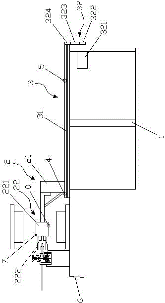
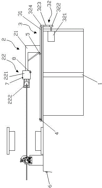
[0022] Please refer to figure 1 , figure 2 , the present invention provides an automatic clamping and stretching device, comprising: a frame 1, a clamping fixture 2 and a stretching device 3 arranged on the frame 1, the frame 1 is a metal frame, and the pulling The extension device 3 includes a guide rod 31 and a drive unit 32, the drive unit 32 is in transmission connection with the guide rod 31, and the drive unit 32 is composed of a servo motor 321, a first gear 322 connected with the rotor of the servo motor 321, The second gear 324 is connected to the first gear 322 through the belt 323. The servo motor 321 is provided with a power switch (not shown), and the power switch is activated, and the servo motor 321 drives the first gear. 322 operation, the first gear 322 drives the second gear 324 to rotate through the belt 323 under the transmi...


PUM


Abstract

The invention discloses an automatic wire clamping and drawing device. The automatic wire clamping and drawing device comprises a rack, and a wire clamping jig and a drawing device, which are arranged on the rack, wherein the drawing device comprises a guide rod and a driving unit, the driving unit is in transmission connection with the guide rod, the wire clamping jig comprises a support movably arranged on the guide rod and a wire clamping device arranged on the support, the wire clamping jig moves forwards and backwards along the guide rod under the action of the driving unit, and the wire is clamped and drawn by the wire clamping device. According to novel automatic auxiliary equipment provided by the invention, through the cooperation work of the wire clamping jig and the drawing device, a wire material can be automatically clamped and drawn to an appointed position during the injection molding of a power supply wire tail clip, then, automatic die assembly and injection molding are carried out, and the molding position of the tail clip can be accurately positioned. Compared with traditional manual locating, the automatic wire clamping and drawing device greatly increases the work efficiency and reduces manual operation time. By using the automatic wire clamping and drawing device, locating is more accurate, size errors are small, and the requirements of factories are met.

Description

technical field [0001] The invention relates to a new type of automatic auxiliary equipment, in particular to an automatic thread clamping and stretching device. Background technique [0002] At present, the tail clips of the power cord are manually placed in a single line during molding and injection molding, and the single line is inserted into the mold line groove, and it is necessary to manually measure the size with a ruler to determine the molding position of the tail clip. This operation method has low efficiency and large dimensional errors. , Manual operation time waste and other defects. [0003] Therefore, it is necessary to develop an automatic auxiliary equipment that can replace manual operation, thereby improving efficiency, reducing manual operation time, and reducing dimensional errors. Contents of the invention [0004] The purpose of the present invention is to overcome the deficiencies of the prior art, and to provide a wire rod that can be automatical...

Claims


Application Information

Patent Timeline
IPC IPC(8): B29C45/14
CPCB29C45/14008B29C45/14065
Inventor 向国东周恩勇
Owner 深圳市国信达科技股份有限公司
Why Eureka
Try Eureka