Peelable thin-film type deicing method for airplanes

A film-type and thin-film technology, which is applied in the field of aircraft peelable film-type deicing, can solve the problems of infeasibility and difficulty in deicing

Inactive Publication Date: 2016-11-23
姚舜 +2
View PDF0 Cites 1 Cited by
  • Summary
  • Abstract
  • Description
  • Claims
  • Application Information

AI Technical Summary

Problems solved by technology

[0002] At present, aircraft deicing is a difficult problem, especially when the aircraft is icing during high-altitude flight, it is even more

Method used


Image

  • Peelable thin-film type deicing method for airplanes
  • Peelable thin-film type deicing method for airplanes
  • Peelable thin-film type deicing method for airplanes

Examples


Embodiment 1

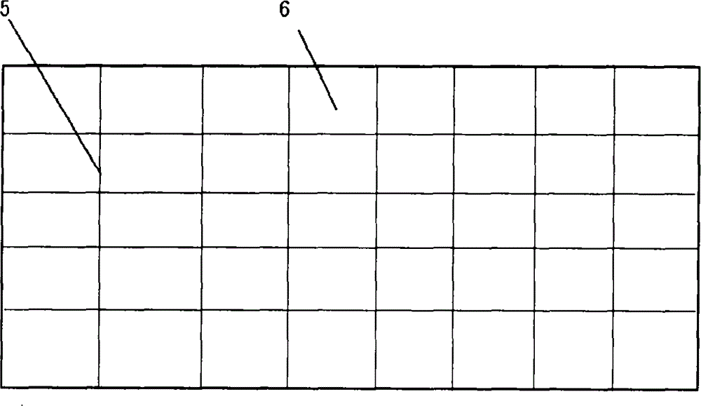
[0022] On the surface of the aircraft shell 1, a large piece or even a whole film 4 is spliced ​​with a plurality of film segments 6, and each film segment 6 is independent, and a segmented splicing line 5 is formed between adjacent blocks; corresponding to the segmented splicing line 5 At the place, there is a thermal cutting line 8 composed of resistance wire; between the film 4 and the aircraft shell 1, and between the film 4 and the film 4, there is a heating layer 3; when the aircraft shell 1 freezes, turn on the heating Layer 3 heats the power supply 9, and connects the thermal cutting line 8 that is made up of resistance wire, like this, the thermal cutting line 8 melts the ice layer 11 from the block splicing line 5 or the dividing line 7, and makes the ice layer 11 form and film The melting line matched by the block stitching line 5 of the block 6, that is, the ice layer is cut into a small piece of flake ice layer by the thermal cutting line 8. At this time, due to th...

Embodiment 2

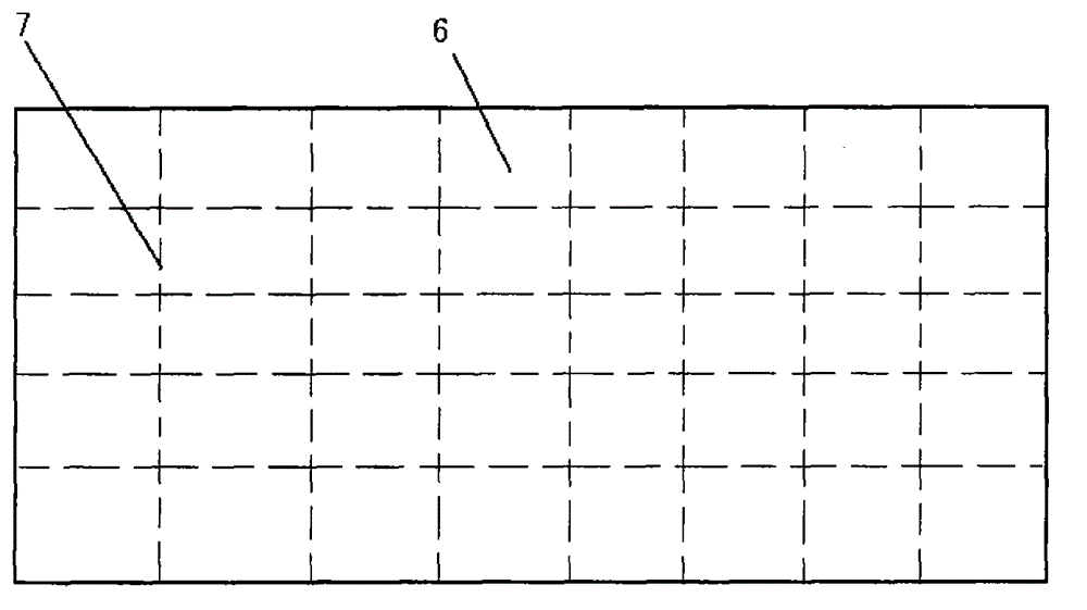
[0024] Embodiment 2 is roughly the same as Embodiment 1, and the difference is that what Embodiment 2 used was a large film with dividing line 7. After freezing on the aircraft shell 1, the heating power supply 9 and thermal cutting of the heating layer 3 were switched on. Line 8 power supply, film 4 is torn and peeled off from parting line 7, and is also torn and peeled off from parting line 7 with a piece of ice layer 11.

[0025] The film 4 is any stickable film. The dividing line 7 is physically divided or chemically divided.

Embodiment 3

[0027] Figure 5 Middle, 5. Block splicing line, 6. Film block, 12. Folding protrusion. The folding protrusion 12 is exactly to fold the edge at the edge of the film segment 6 to form a folding protrusion 12 at a certain angle with the film segment 6 plane. The function of the folding protrusion 12 is that after the film segment 6 freezes, The folded projections 12 tightly covered by the ice layer 11 can be torn off from the splicing line 5 by the falling ice layer.


PUM


Abstract

In order to overcome the defects existing in a conventional deicing technique for airplanes, the invention provides a peelable thin-film type deicing method for the airplanes. The peelable thin-film type deicing method comprises the following step of pasting and covering a layer or layers of thin films which can be peeled due to reduced viscidity after being electrically heated, at positions wherein icing is easy to occur on a shell of an airplane, wherein the thin films along with icing on the thin films can be peeled together, so that the effect of deicing is achieved. The thin films are designed into being spliced, an impression or a cutting line, which is easy to tear, can also be arranged on a large thin film, and viscose of which the viscidity is easy to reduce after being heated is selected as glue for pasting and covering the thin films. Electric heating layers are arranged between the thin films and an airplane body and between the thin films, and are electrically connected with a heating power supply. When a temperature sensor or an inductor induces that ice is formed on the airplane, the heating power supply is switched on, the heating layers are uniformly heated, and the heated heating layers conduct heat to the glue of the thin films, so that the viscidity of the glue is reduced, and the thin films are torn along grid lines and are peeled off along with icing layers on the thin films; and therefore, the purpose of deicing for the airplanes is achieved.

Description

technical field [0001] The technology belongs to the field of aircraft deicing, and further relates to an aircraft peelable film type deicing method. technical background [0002] At present, aircraft deicing is a difficult problem, especially when the aircraft freezes during high-altitude flight, deicing while flying is even more difficult. There are technologies that claim to heat the skin of the aircraft, but it is not feasible for practical application. Contents of the invention [0003] In order to overcome the deficiencies of the existing aircraft deicing technology, the present invention proposes an aircraft peelable film type deicing method, which is to paste one or more layers on the parts of the aircraft shell that are easy to freeze and reduce the viscosity when heated by electricity. Therefore, the film that can be peeled off, the film peels off the icing on it together, and the deicing effect is achieved. [0004] The technical scheme for realizing the prese...

Claims


Application Information

Patent Timeline
IPC IPC(8): B64D15/12
Inventor 姚舜程子剑赵鹏游雅岳琦修梁栋姚连艺璇姚志勇
Owner 姚舜
Why Eureka
Try Eureka