Optoelectronic pod

A technology of photoelectric pods and outer parts, applied in the aviation field, can solve problems affecting the flight status and flight efficiency of aircraft, and complicated collection methods

Active Publication Date: 2016-11-23
EWATT TECH CO LTD
View PDF7 Cites 1 Cited by
  • Summary
  • Abstract
  • Description
  • Claims
  • Application Information

AI Technical Summary

Problems solved by technology

Therefore, there is usually a gimbal fixed at the bottom of the fuselage. However, the gimbal itself is usually a "static" operation, that is, it can only be aimed at one direction for information collection, and when other angles need to be collected, often by adjusting the flight of the aircraft The attitude completes the information collection action. This kind of collection method with the aircraft as the adjustment object is too cumbersome, and the real-time adjustment of the aircraft's flight attitude can also easily affect the flight status and flight efficiency of the aircraft.

Method used


Image

  • Optoelectronic pod
  • Optoelectronic pod
  • Optoelectronic pod

Examples


Embodiment approach

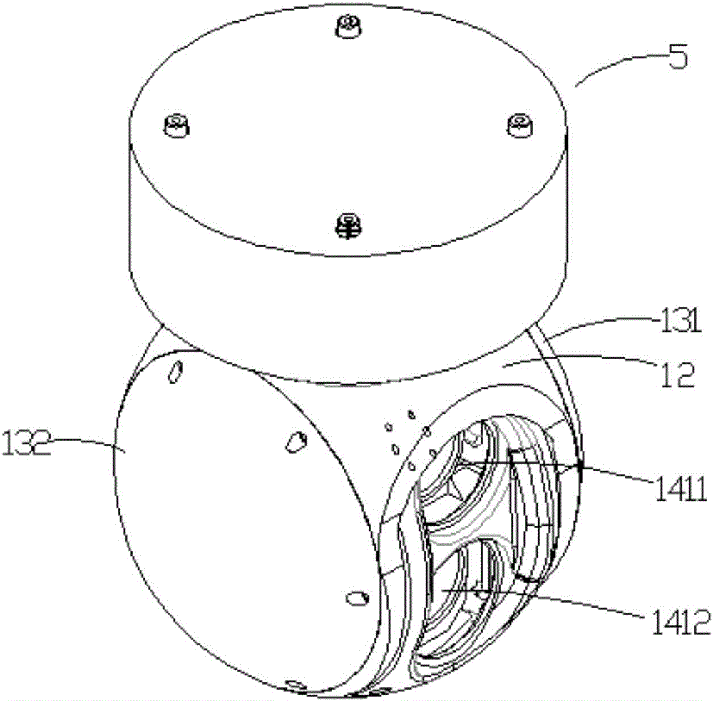
[0068]In the embodiment of the present invention, it needs to be added that in addition to installing the imaging device 3 in the inner housing, other devices can also be installed at the same time, for example, an infrared device 4 for lighting can be fixed in the inner housing 11 , so that the infrared device 4 is used in conjunction with the camera device to realize nighttime photography. At this time, a second projection window 1412 can be opened on the third cover body 141 , so that the infrared device 4 communicates with the outside world through the second projection window 1412 . At the same time, a mounting groove 117 is provided in the middle of the inner casing 11, and a partition 118 is provided on the mounting groove 117, so that the infrared device 4 and the camera device 3 are mounted on the partition 118. the upper and lower sides. As an embodiment of the present invention, the camera device 3 may be a video camera; the infrared device 4 may be an infrared ins...


PUM


Abstract

The invention discloses an optoelectronic pod and belongs to the technical field of unmanned aerial vehicles. The optoelectronic pod comprises a rotating main body and a first driving member, wherein the rotating main body is rotationally fixed on outside loading equipment; a photographic device for acquiring information is fixed in the rotating main body; the first driving member is fixed on the rotating main body and is movably connected with the photographic device. The optoelectronic pod disclosed by the invention is arranged on the outside loading equipment (such as an aircraft), so that multi-angle acquisition of image and video information in a horizontal direction and a vertical direction is finished on the premise of not influencing flying state and flying efficiency of the aircraft. The optoelectronic pod has the characteristics of simple structure and wide application range.

Description

technical field [0001] The invention belongs to the field of aviation technology, in particular to a photoelectric pod. Background technique [0002] Loading equipment is various in the prior art, is exactly a kind of in the loading equipment as the aircraft used for flight, and aircraft (English: aircraft) refers to the relative movement (not by air to the ground that takes place through airframe) reaction) to obtain aerodynamic lift-off machines. Including airships, airplanes, gliders, rotorcraft, helicopters, orthopters, tiltrotors, etc. [0003] During the flight of an aircraft, due to operational requirements, it is often necessary to collect relevant information on the way in real time, such as images and video information along the way. Therefore, there is usually a gimbal fixed at the bottom of the fuselage. However, the gimbal itself is usually a "static" operation, that is, it can only be aimed at one direction for information collection, and when other angles ne...

Claims


Application Information

Patent Timeline
Patent Type & Authority Applications(China)
IPC IPC(8): B64D47/00B64D47/08
CPCB64D47/00B64D47/08
Inventor 赵国成赵涛张凯叶柳
Owner EWATT TECH CO LTD
Why Eureka
Try Eureka