Automatic C-shaped track core bundle strapping machine

An automatic binding and core technology, which is applied to the parts of the binding machine, binding objects, binding materials, etc., can solve the problems of low reliability, large binding edge distance, long working time of wire walking, etc.

Active Publication Date: 2016-11-23
LIAONING DONGSHENG PRECISION MACHINERY CO LTD
View PDF9 Cites 8 Cited by
  • Summary
  • Abstract
  • Description
  • Claims
  • Application Information

AI Technical Summary

Problems solved by technology

The wire-feeding process of the original core automatic binding machine requires two servo motors, two wire-feeding mechanisms to clamp steel wires, and the minimum edge distance is above 100mm. shortcoming

Method used


Image

  • Automatic C-shaped track core bundle strapping machine
  • Automatic C-shaped track core bundle strapping machine
  • Automatic C-shaped track core bundle strapping machine

Examples


Embodiment Construction

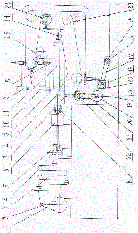
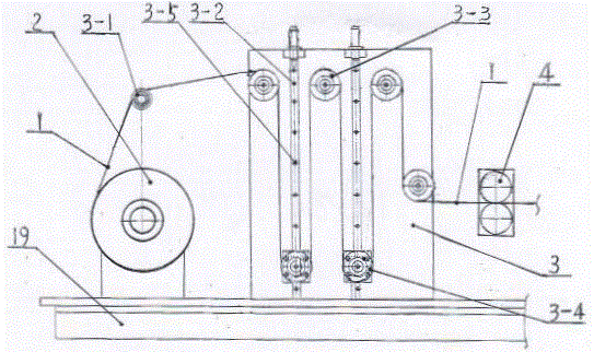
[0014] Examples, see attached Figure 1~6, The C-type track core automatic binding machine is provided with an uncoiling mechanism 2 on the upper left side of the support 19, a buffer guide wheel 3-1 is provided above the uncoiling mechanism 2, and a buffer guide wheel 3-1 is arranged on the right side of the uncoiling mechanism 2. There is a buffer mechanism, and the buffer mechanism is to vertically and parallelly fix two adjustment frames 3-2 on the buffer mechanism support plate 3, and a plurality of adjustment holes 3-5 are symmetrically arranged on the two adjustment frames 3-2. Adjustable buffer wheel 3-4 is housed in the hole 3-5, above the buffer mechanism support plate 3, three buffer wheels 3-3 are equipped with equidistant between the two adjustment frames 3-2 and the outside, on the buffer mechanism support plate 3 A buffer wheel 3-3 is equipped with in the middle part on the left side. On the support 19 on the left side of the buffer mechanism support plate 3, a...


PUM


Abstract

The invention belongs to the machine industry, and particularly relates to an automatic C-shaped track core bundle strapping machine. An uncoiling mechanism (2) is arranged above the left portion of a machine base (19). A temporary storage mechanism is arranged on the right side of the uncoiling mechanism (2). A wire feeding mechanism and a straightening mechanism are arranged on the part, on the right side of a buffering mechanism supporting plate (3), of the machine base (19). A movable workbench (9) and a bundle strapping mechanism are arranged on the right side of a wire conveying mechanism (6). A rack (19-1) is arranged on the right side of the machine base (19). The movable workbench (9) is arranged at the middle portion of the rack (19-1). The rack (19-1) is provided with a plurality of guiding wheels (23) according to the C-shaped walking track of a steel wire (1). Vertical pneumatic clamping fingers (10) are arranged on the guiding wheel (23) at the left upper corner in a symmetrically-vertical and left-horizontal manner and connected with the guiding wheels (23) through bilateral chains (24). A servo motor is adopted in the automatic C-shaped track core bundle strapping machine for finishing one-time wire feeding, the wire feeding time is shortened, and wire penetrating, wire feeding, core bundle strapping, a displacement mechanism, resetting and the like are all automatically controlled.

Description

technical field [0001] The invention belongs to the machinery industry, in particular to a C-shaped track core automatic binding machine. Background technique [0002] The original core automatic binding machine clamps the steel wire from the wire release position through a horizontal wire-feeding mechanism, and moves it horizontally and rightward to the designated position on the lower side of the core body, and the second wire-feeding mechanism moves vertically down on the right side of the core body Go to the bottom of the core body, clamp the steel wire sent by the first wire feeding mechanism and lift it above the core body, and then move horizontally to the left to the wire binding position. The first wire feeding mechanism moves left horizontally to the initial position, while the wire feeding mechanism reversely tightens the steel wire, the binding mechanism enters the wire feeding position, the steel wire enters the upper gripping finger of the binding mechanism, th...

Claims


Application Information

Patent Timeline
Patent Type & Authority Applications(China)
IPC IPC(8): B65B13/04B65B13/18B65H51/04B21F1/02
CPCB21F1/02B65B13/04B65B13/184B65H51/04B65H2701/39
Inventor 翟佐玲姚继权毛冬菊何绍华倪杰
Owner LIAONING DONGSHENG PRECISION MACHINERY CO LTD
Why Eureka
Try Eureka