
A hydraulically telescopic conveying arm

A technology of hydraulically telescopic and conveying arms, which is applied in the direction of conveyors, conveyor objects, transportation and packaging, etc., and can solve problems such as unstable shaking of the hull, potential safety hazards, and failure of the four-bar mechanism

Active Publication Date: 2018-03-16
YUANJIANG JINGYI SCI & TECH MACHINERY MFG CO LTD
View PDF7 Cites 0 Cited by
  • Summary
  • Abstract
  • Description
  • Claims
  • Application Information

AI Technical Summary

Problems solved by technology

The disadvantages are: this kind of folding sand unloading arm has a heavy load and complex structure, and the four-bar mechanism cannot accurately control it, and when the arm frame is opened and closed, there will be a large overturning moment. It causes the hull to shake and become unstable, or even capsize, which also poses a safety hazard

Method used


Image

  • A hydraulically telescopic conveying arm
  • A hydraulically telescopic conveying arm
  • A hydraulically telescopic conveying arm

Examples


Embodiment Construction

[0020] The present invention will be described in further detail below in conjunction with the accompanying drawings and specific embodiments.

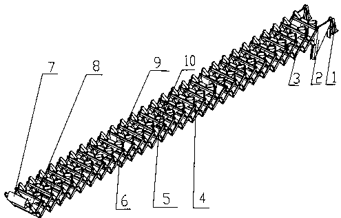
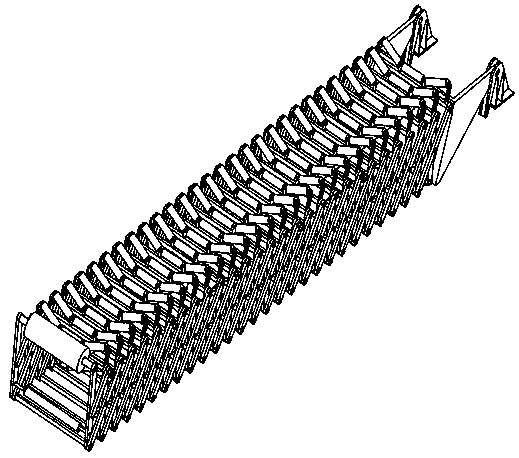
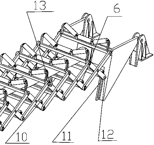
[0021] attached figure 1 Among them, a hydraulically telescopic conveying arm specifically includes a conveying arm base 1, a conveying arm connecting plate 2, a scissors fork conveying arm frame 3, a hydraulic cylinder 4, an upper carrying idler 5, a lower return idler 6, an upper reversing The drum 7, the lower reversing drum 8, the upper boom cross bar 9, and the lower boom cross bar 10.

[0022]In a specific embodiment, the scissors fork delivery arm frame 3 is a left-right symmetrical structure hinged by a plurality of rectangular steel bars. Extend the length of the delivery arm; the scissors fork delivery arm frame 3 is installed on the delivery arm connecting plate 2, and the connection mode between it and the delivery arm connecting plate 2 is hinged; the upper and lower hinges of each scissor fork are provided with The boo...


PUM


Abstract

The invention provides a hydraulic telescopic conveying arm and particularly relates to a conveying arm used for a self-discharging ship conveyer. The hydraulic telescopic conveying arm specifically comprises a conveying arm base, a conveying arm connecting plate, a shear-fork conveying arm frame, a hydraulic oil cylinder, a carrier roller, a reversing roller and an arm rest cross rod. The shear-fork conveying arm frame is of a symmetrical structure, one end of the shear-fork conveying arm frame is fixed to the conveying arm connecting plate hinged to a ship body, the other end of the shear-fork conveying arm frame is connected with the reversing roller, and steel wire rope hanging points are evenly arranged on hinge pins on the two sides. A multi-stage telescopic hydraulic cylinder is adopted to serve as the hydraulic oil cylinder; a terminal piston rod, away from the ship head, of the hydraulic oil cylinder is connected with the arm rest cross rod on the upper layer, and the end, close to the ship head, of the hydraulic oil cylinder is connected with the conveying arm connecting plate; and horizontal unfolding and folding of the conveying arm can be achieved through the stretching and contacting of the hydraulic oil cylinder. The hydraulic telescopic conveying arm has the advantages that the stretching and contracting travel of the whole arm is long, and the variation amplitude range of the whole arm is wide; the structure is simple and compact, the self weight is low, and operation is easy and convenient; and the influence of folding and unfolding of an arm rest on the stability of the ship body is small, and a ship deck is not prone to fatigue cracks.

Description

technical field [0001] The invention relates to a conveying arm of a self-unloading sand transport ship, in particular to a hydraulic telescopic conveying arm. Background technique [0002] With the booming economy in the Xiangjiang River area, the construction of roads and bridges and the further development of local real estate and other construction industries, the demand for construction sand has increased rapidly, so the inland river transportation industry for sand mining and sand transportation has also flourished. stand up. Especially in recent years, sand carriers equipped with self-unloading equipment have been widely used because of their high production efficiency and convenient unloading. With the rapid development of shipbuilding technology, the tonnage of self-unloading ships generally reaches the thousand-ton class, and the length of the ships themselves exceeds 60 meters, and some even reach 100 meters. In the past, in order to adapt to the unloading funct...

Claims


Application Information

Patent Timeline
Patent Type & Authority Patents(China)
IPC IPC(8): B65G21/14B65G41/00
CPCB65G21/14B65G41/001
Inventor 尹来容杨硕刘鑫张志勇胡林张旭
Owner YUANJIANG JINGYI SCI & TECH MACHINERY MFG CO LTD
Learn More