Supercharge Your Innovation With Domain-Expert AI Agents!

Remotely controlled slow-descent lock

A technology of remote control lock and remote control key, which is applied in the direction of hoisting device and hoisting device, etc. It can solve the problems of being far behind bicycles, unable to park outdoors, and can only be carried with you. Simple and reasonable effect

Inactive Publication Date: 2016-11-23
曾玮
View PDF0 Cites 0 Cited by
  • Summary
  • Abstract
  • Description
  • Claims
  • Application Information

AI Technical Summary

Problems solved by technology

[0002] The problem of stolen bicycles has been difficult to solve
In recent years, portable means of transportation such as electric unicycle balance vehicles, electric scooters, etc. have become popular. They seem small and light and can be carried around, and can also be used in buses and subways. It is very convenient, but the biggest problem is that they cannot be parked outdoors. You can only carry it with you when you travel, but it is far less convenient than a bicycle that can be parked anywhere

Method used


Image

  • Remotely controlled slow-descent lock
  • Remotely controlled slow-descent lock
  • Remotely controlled slow-descent lock

Examples


Embodiment 1

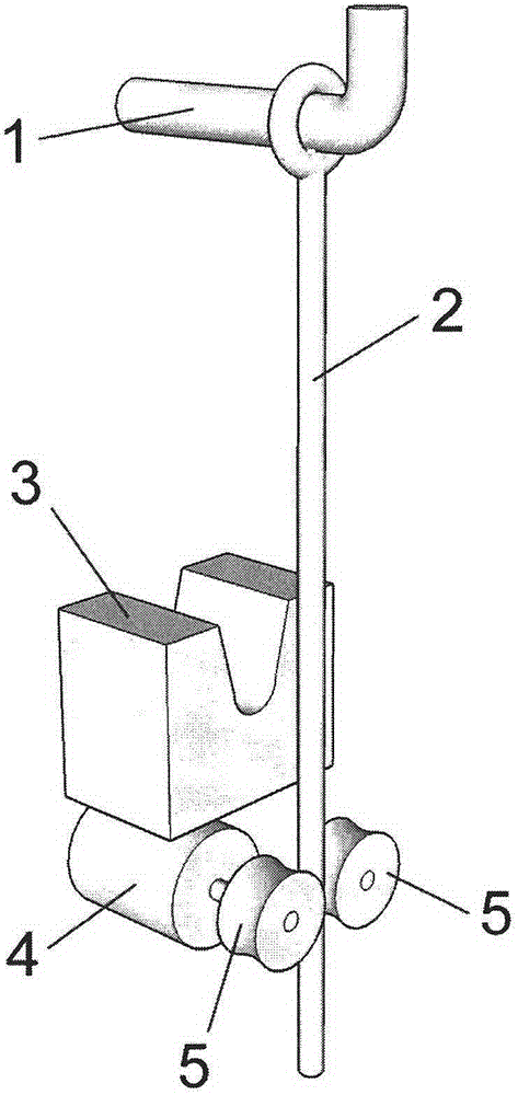
[0017] Example 1. See figure 1 , the remote control slow-down lock of this example includes locking mechanism 3, slow mover 4, rope clamping wheel 5. Wherein the rope clamp wheel 5 can clamp the hanging rope 2 hanging down from the suspension point 1. The slow mover 4 is actually a motor, so the lock body can be raised along the suspension rope 2 under its driving. For the sake of safety, the ascent process can be controlled by the remote control key instead of automatically rising to the top. When rising to the highest point, the suspension point 1 is locked after being embedded in the U-shaped groove at the top of the locking mechanism 3, and the lock stays at a high place that people cannot reach with the locked article. After the locking mechanism 3 is unlocked by remote control, the automatic slow down is realized by limiting the rotating speed of the slugger 4, and the lock can bring the locked item down again. The lock in this example also includes other components ...

Embodiment 2

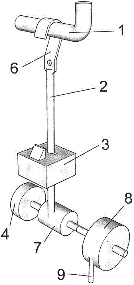
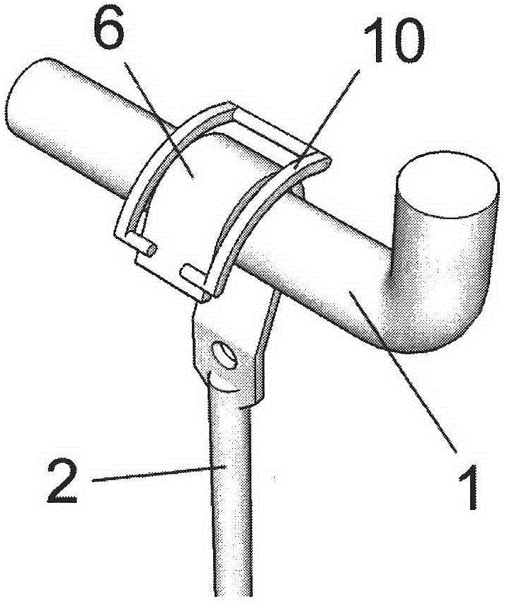
[0018] Example 2. See figure 2 , the remote control slow down lock of this example comes with sling 2, one end is connected with hook 6, and the other end is wound on the winding shaft 7 inside it. There is also a power backguy 9 in addition, which is wound on the large bobbin 8. The bobbin 7 and the large bobbin 8 can be linked or separated by a clutch mechanism. When linked, the user can pull out the pull wire 9 to make the large winding shaft 8 drive the winding shaft 7 to wind the suspension rope 2, so that the lock body rises. When it rises to the highest point, the hook 6 is locked after being embedded in the locking mechanism 3, and the shape of the locking mechanism 3 also ensures that the hook 6 cannot be disengaged from the suspension point 1. Then the user releases the backguy 9, and the large bobbin 8 can be reversed and retracted into the lock again. (can be equipped with winding spring on the big bobbin 8, this moment in addition bobbin 7 and big bobbin 8 se...


PUM


Abstract

The invention relates to the structure of a remotely controlled slow-descent lock. Through the structure of the remotely controlled slow-descent lock, an article can be locked on a suspension point 1 at a high position that a person cannot touch. After the structure of the remotely controlled slow-descent lock is unlocked in a remote control manner, the lock with the locked article slowly descends to a height, which can be touched by a user, along a lifting rope 2 and under the action of a slow actuator 4. Next, the user can make a hook 6 be separated from the suspension point 1 in an ejection manner through a way of pulling the lifting rope 2. In the process of locking the lock at the suspension point 1, first, the hook 6 is hung on the suspension point 1, afterwards, and a big spool 8 is enabled to drive a spool 7 to twine the lifting rope 2 through pulling out a power pull wire 9 in a lock body, so that the lock body ascends. After the lock is locked at the suspension point 1, the power pull wire 9 can be also automatically wound by the big spool 8 to be retracted in the lock body.

Description

technical field [0001] The invention relates to a structure of a lock, which is characterized in that it can be locked at a high suspension point, and after being unlocked by a remote control key, it can be slowly lowered to a height accessible to users along a rope. Background technique [0002] The problem of stolen bicycles has always been difficult to solve. Tracing it to its cause is because no matter what kind of lock is adopted, it is difficult to resist technical unlocking or violent destruction 100%. However, if you change your thinking, if the locked bicycle is in a high place that cannot be reached by people, then the problem of bicycle theft can be fundamentally solved. [0003] Of course, it's not just about stolen bikes. In recent years, portable mobility tools such as electric unicycle balance bikes, electric scooters, etc. have become popular. They seem small and light and can be carried around, and they can also be used in buses and subways. It is very con...

Claims


Application Information

Patent Timeline
Patent Type & Authority Applications(China)
IPC IPC(8): B66F19/00
Inventor 曾玮
Owner 曾玮
Features
  • R&D
  • Intellectual Property
  • Life Sciences
  • Materials
  • Tech Scout
  • Unparalleled Data Quality
  • Higher Quality Content
  • 60% Fewer Hallucinations
Learn More