Connection structure and method of prefabricated column and beam-slab joints in concrete frame structure

A frame structure and prefabricated column technology, applied in building construction, construction, etc., can solve the problems of limited working space, difficult positioning, difficult operation, etc., to reduce the amount of concrete pouring, reduce the time for drying and hardening, and improve the shear resistance. performance effect

Active Publication Date: 2018-06-05
NINGBO PRECA CONSTR TECH CO LTD
View PDF5 Cites 0 Cited by
  • Summary
  • Abstract
  • Description
  • Claims
  • Application Information

AI Technical Summary

Problems solved by technology

First of all, after the prefabricated beams are installed in place, the joint area, that is, the area between the two prefabricated beams, is relatively narrow. In this area, when workers connect the negative moment longitudinal force reinforcement bars extending from the bottom of the prefabricated beams into the section of the prefabricated columns , the operation is difficult, especially when there are four prefabricated beams perpendicular to each other in the node area, the work space is more limited, and the connection operation construction is more difficult; secondly, the amount of concrete poured on site is still relatively large, and waiting for it to dry hard will delay construction period; moreover, the upper and lower prefabricated columns are connected by inserting and anchoring the protruding longitudinal steel bars of the lower precast column into the slurry anchor sleeve of the upper precast column. The concrete between the stress reinforcements must reach a certain thickness and ensure uniform thickness. In this way, the inner diameter of the grout anchor sleeve can only be designed to be much larger than the outer diameter of the longitudinal stress reinforcement. In this way, when the upper prefabricated column is hoisted in place , it is difficult to ensure that the longitudinally stressed steel bar at the bottom is exactly on the central axis of the upper slurry anchor sleeve, and the positioning is difficult, and it is even more difficult to ensure that the thickness of the concrete between the longitudinally stressed steel bar and the slurry anchor sleeve is uniform. The connection effect of the root prefabricated column is not firm

Method used


Image

  • Connection structure and method of prefabricated column and beam-slab joints in concrete frame structure
  • Connection structure and method of prefabricated column and beam-slab joints in concrete frame structure
  • Connection structure and method of prefabricated column and beam-slab joints in concrete frame structure

Examples


Embodiment Construction

[0023] The present invention will be further described below in conjunction with the accompanying drawings and specific embodiments.

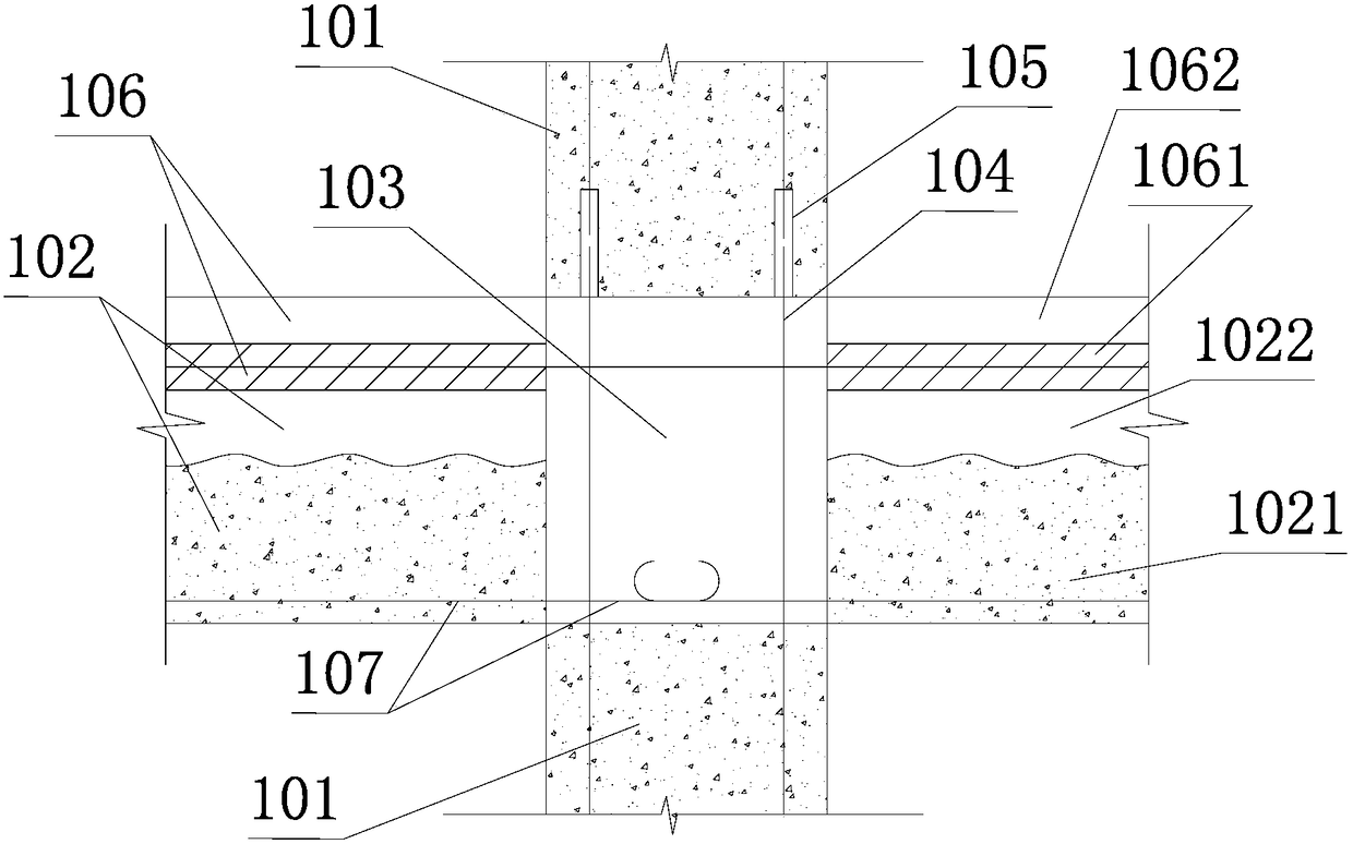
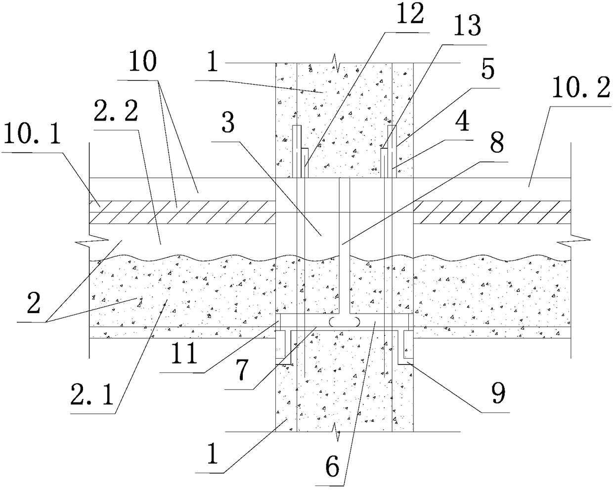
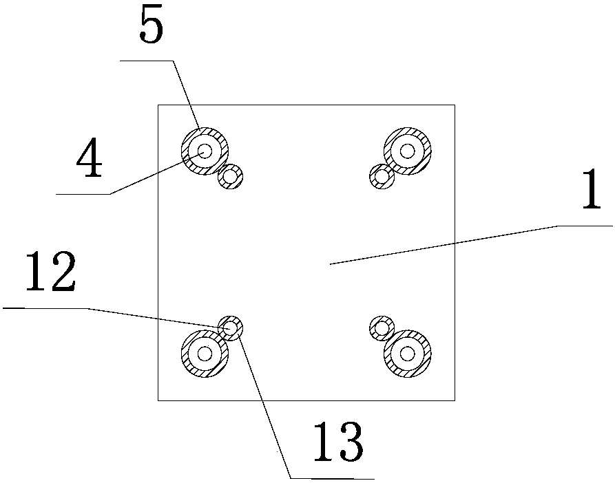
[0024] Such as figure 2 , image 3As shown, the connection structure between the prefabricated column and the beam-slab node of the concrete frame structure of the present invention includes the prefabricated column 1 below, the prefabricated column 1 above, the composite beam 2 on both sides and the upper and lower prefabricated columns 1 and two The node area 3 between the side laminated beams 2 is poured with concrete. Sometimes, there are not only two composite beams 2 in the node area 3, but four composite beams 2 perpendicular to each other are butted. Each composite beam 2 is formed by laminating a lower prefabricated beam 2.1 and an upper cast-in-place beam 2.2. The lower prefabricated column 1 is anchored with a vertical stressed steel bar 4 , and the vertical stressed steel bar 4 passes through the concrete in the node area 3 and ...


PUM


Abstract

The invention discloses a connecting structure and method for precast column and beam and slab joints of a concrete frame structure. The structure comprises upper and lower precast columns (1), laminated beams (2) on the two sides and a joint area (3). The top of the lower precast column (1) is flush with the laminated faces of precast beams (2.1) of the laminated beams (2) on the two sides, a transverse metal bellows (6) is arranged in the lower precast column (1) in a penetrating mode, and negative moment longitudinal force-bearing steel bars (7) at the bottoms of the precast beams (2.1) on the two sides stretch into and are anchored in the metal bellows (6). A grout pipe (8) communicated with the metal bellows (6) is anchored in the joint area (3). The method is characterized in that all the negative moment longitudinal force-bearing steel bars (7) at the bottoms of the precast beams (2.1) on the two sides stretch into the metal bellows (6) of the lower precast column (1) and are anchored. By means of the structure and the method, it can be avoided that operation at joints is difficult due to the narrow space, and the use amount of cast-in-place concrete can be reduced.

Description

technical field [0001] The invention relates to a construction method and technology at a node of a concrete frame structure, in particular to a connection structure and a connection method at a node of a prefabricated column of a concrete frame structure, a composite beam and a composite slab. Background technique [0002] In recent years, the country has vigorously promoted the process of building industrialization and prefabrication. As far as the concrete frame structure is concerned, its prefabricated components include prefabricated columns, laminated beams and laminated slabs. Most of the prefabricated columns are prefabricated in the factory, only the joints need to be cast in-situ concrete, and, in order to realize the butt joint of the upper and lower prefabricated columns, multiple vertical columns are pre-buried at the lower end of each prefabricated column. For the grout anchor sleeve, a number of vertical reinforced steel bars are pre-embedded at the top of ea...

Claims


Application Information

Patent Timeline
Patent Type & Authority Patents(China)
IPC IPC(8): E04B1/21
CPCE04B1/21
Inventor 陈静吴佳雄周林根李英蒋义张忠杰
Owner NINGBO PRECA CONSTR TECH CO LTD
Why Eureka
Try Eureka