
Patsnap Eureka
For R&D, Patsnap Eureka makes reading and utilizing patents & technical documents easy.
Patsnap Eureka AIR
Designed for self-driven R&D workflows. Generate viable solutions, solve complex R&D challenges, empower your innovation with AI.

Patsnap Eureka Materials
Designed for material experts only. Revolutionize your material R&D, from search, analyze, to developing new materials.

TechResearch
Generate reliable direction feasibility study reports for your R&D in just a few steps.

TechSeek
Discover and master advanced knowledge NOW. Basics, ideas, possibilities, all at once.

TechMind
As an expert in R&D Theories, TechMind can generates customized viable solutions instantly.

TechRisk
Analyze your overall solution with one click, know your potential R&D risks in advance.

TechMonitor
Get weekly tech updates, stay abreast of the latest tech innovations and key insights.
Pollution-free buoyancy power generator
A buoyant block, floating body technology, used in hydroelectric power generation, engine components, machines/engines, etc.
- Summary
- Abstract
- Description
- Claims
- Application Information
AI Technical Summary
Problems solved by technology
Method used
Image

Examples
Embodiment Construction
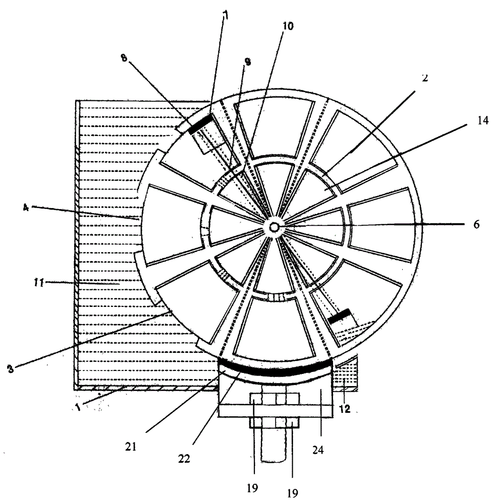
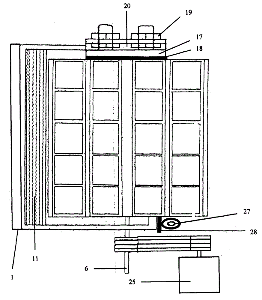
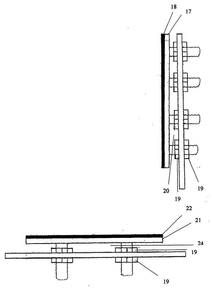
[0009] The specific embodiment of the patent of the present invention is further described in detail in conjunction with the accompanying drawings:
[0010] Depend on figure 1 , figure 2 , image 3 The pollution-free buoyancy generator of the present invention patent includes: the rotating shaft 6 is equipped with a closed head, divided and opened, and the finishing turning wheel 2 is half upright in the liquid storage tank 1. The radius of the turning wheel 2 can be 3 meters to 300 meters according to the needs. , the rotating wheel 2 is composed of several equal parts of open compartments, each equal part of the open compartment has a large buoyancy block 3 and a small buoyancy block 14, and each group of symmetrical buoyancy blocks has a connecting rod 9 connected to a symmetrical piston 7, and a trachea 10 connected to a symmetrical gas cylinder 8 form a movable floating body, which is suitable for making circles and other movable floating bodies according to the needs,...
PUM
 Abstract
Description
Claims
Application Information
 - R&D Engineer
- R&D Manager
- IP Professional
- Industry Leading Data Capabilities
- Powerful AI technology
- Patent DNA Extraction
Browse by: Latest US Patents, China's latest patents, Technical Efficacy Thesaurus, Application Domain, Technology Topic, Popular Technical Reports.
© 2024 PatSnap. All rights reserved.Legal|Privacy policy|Modern Slavery Act Transparency Statement|Sitemap|About US| Contact US: help@patsnap.com