
Vehicle lighting device and fabrication method thereof

A technology for lighting devices and vehicles, applied in lighting devices, fixed lighting devices, cooling/heating devices of lighting devices, etc., can solve problems such as small contact area and low heat dissipation efficiency, and achieve improved heat dissipation efficiency and good heat conduction effect Effect

Inactive Publication Date: 2016-11-23
CORETRONIC
View PDF6 Cites 0 Cited by
  • Summary
  • Abstract
  • Description
  • Claims
  • Application Information

AI Technical Summary

Problems solved by technology

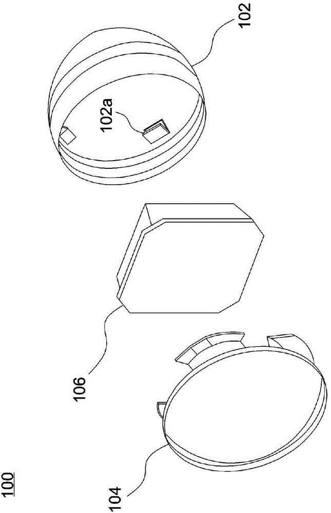
Therefore, the thermal energy of the heat sink 106 can only be conducted to the entire lamp housing 102 via the flange 102a, but the contact area is extremely small, resulting in a lower heat dissipation efficiency

Method used


Image

  • Vehicle lighting device and fabrication method thereof
  • Vehicle lighting device and fabrication method thereof
  • Vehicle lighting device and fabrication method thereof

Examples


Embodiment Construction

[0025] The aforementioned and other technical contents, features and effects of the present invention will be clearly presented in the following detailed description of the embodiments with reference to the drawings. The directional terms mentioned in the following embodiments, such as: up, down, left, right, front or back, etc., are only referring to the directions of the drawings. Accordingly, the directional terms are used to illustrate and not to limit the invention.

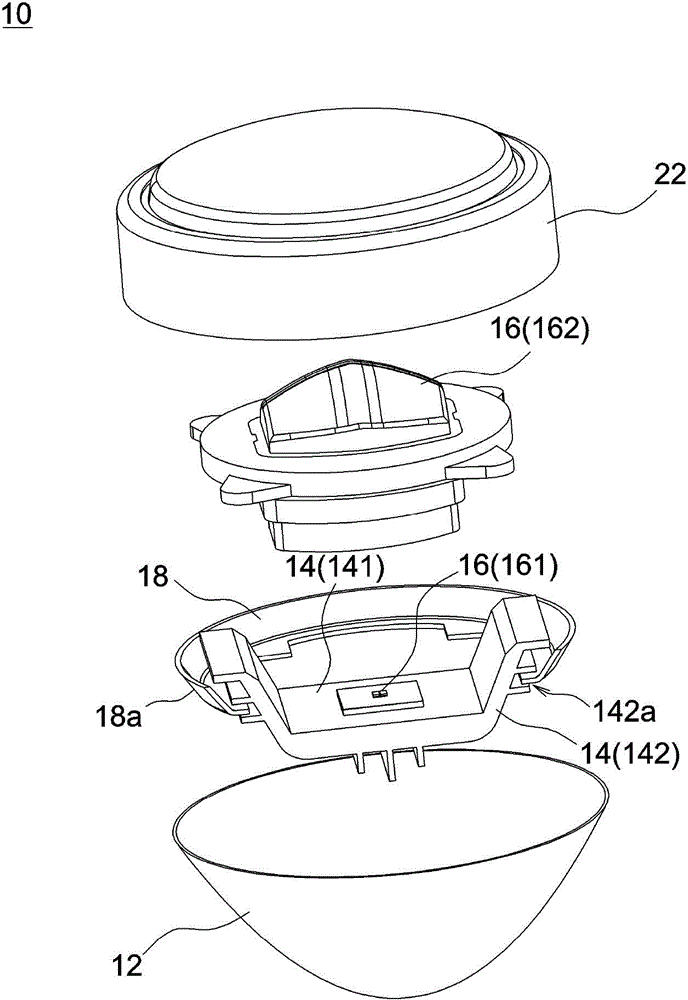
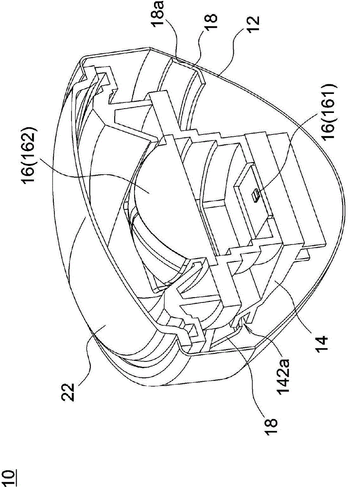
[0026] figure 2 It is an exploded view of components of a vehicle lighting device 10 according to an embodiment of the present invention, image 3 for figure 2 The cross-sectional schematic diagram of the vehicle lighting device after assembly. Such as figure 2 and image 3 As shown, a vehicle lighting device 10 includes a lamp housing 12, a heat sink 14, a light source assembly 16 and a flexible member 18, the heat sink 14 is accommodated in the lamp housing 12, and the light source assembly 16 is a...


PUM

PropertyMeasurementUnit
Thermal conductivityaaaaaaaaaa
Thicknessaaaaaaaaaa

Abstract

A vehicle lighting device includes a lamp housing, a heat sink, a light source assembly, and a flexible member. The heat sink is disposed inside the lamp housing, and the light source assembly is disposed on the heat sink. The flexible member is inserted between and touches the heat sink and the lamp housing to form a heat dissipation path through the heat sink, the flexible member and the lamp housing in succession.

Description

technical field [0001] The invention relates to a lighting device, in particular to a vehicle lighting device with good heat dissipation efficiency. Background technique [0002] figure 1 It is a schematic diagram of a known vehicle lighting device. Such as figure 1 As shown, spot welding inside the lamp housing 102 of the vehicle lighting device 100 can form a plurality of flanges 102a. After the light source assembly 104 is assembled to the heat sink 106, the heat sink 106 is fixed on the flange 102a of the lamp housing. Therefore, the heat energy of the heat sink 106 can only be conducted to the entire lamp housing 102 through the flange 102a, but the contact area is extremely small, resulting in a low heat dissipation efficiency. [0003] China Taiwan New Patent Announcement No. M482521 discloses a car light structure, which includes a lighting unit, a cooling unit and a waterproof cover. The lighting unit includes a fixing seat, a lens and a luminous element, and th...

Claims


Application Information

Patent Timeline
IPC IPC(8): F21S8/10F21V29/71F21V29/74F21W101/02F21W107/10
CPCF21S41/143F21S41/28F21S41/255F21S45/48
Inventor 简兆南黄子泽赖俊霖
Owner CORETRONIC
Learn More