Descaling system for vapor generator in ironing and cleaning equipment

A technology for steam generators and cleaning equipment, which is applied in the field of ironing and cleaning equipment, and can solve problems such as difficult removal of dirt

Inactive Publication Date: 2016-11-23
CUORI ELECTRICAL APPLIANCES GRP
View PDF11 Cites 8 Cited by
  • Summary
  • Abstract
  • Description
  • Claims
  • Application Information

AI Technical Summary

Problems solved by technology

[0007] The technical problem to be solved by the present invention is to provide a descaling system for the steam generator in the ironing and cleaning equipment in order to overcome the defect that the dirt in the steam generator of the ironing and cleaning equipment is not easy to clean in the prior art

Method used


Image

  • Descaling system for vapor generator in ironing and cleaning equipment
  • Descaling system for vapor generator in ironing and cleaning equipment
  • Descaling system for vapor generator in ironing and cleaning equipment

Examples


Embodiment 1

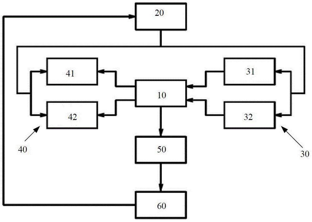
[0037] figure 1 It is a block diagram of the descaling system of the invention for steam generators in ironing and cleaning appliances. like figure 1 As shown, the present invention discloses a descaling system for a steam generator in ironing and cleaning equipment, and the descaling system is connected with the steam generator 10 to form a circulation loop. Wherein, the descaling system includes a control unit 20 , a descaling device 30 , a detection device 40 and a sewage discharge unit 50 . Preferably, the descaling system further includes a water collection box 60 . The control unit 20, the detection device 40, the steam generator 10 and the descaling device 30 are connected in series in sequence to form a circulation loop.

[0038] The control unit 20 is used to control the automatic or manual operation of the descaling system, such as starting descaling, controlling the water level and temperature in the steam generator 10, controlling the startup and running time of...

Embodiment 2

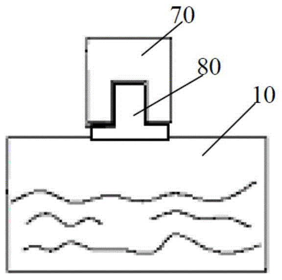
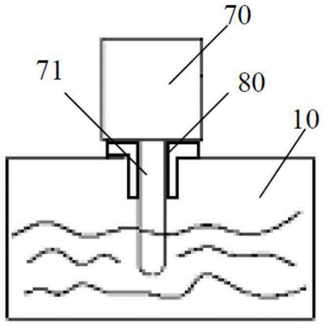
[0046] image 3 Schematic diagram of the installation of the ultrasonic vibrator in the descaling system of the steam generator in ironing and cleaning equipment according to the present invention Figure II . Such as image 3 As shown, the structure of this embodiment is basically the same as that of Embodiment 1, the difference is that: the ultrasonic vibrator 70 is fixed on the steam generator 10 through the fixer 80, and the vibrating end 71 of the ultrasonic vibrator 70 extends to the steam generator. device 10. This further effectively breaks up the dirt. Finally, after the ultrasonic vibration unit tooling is completed, the sewage in the steam generator 10 is discharged by starting the electromagnetic valve in the sewage discharge unit 50, and then the water supply unit 31 supplies water to the steam generator 10 again, thereby completing a coherent dewatering process. Sewage cycle.

[0047] According to the above description of the structure of the descaling syste...


PUM


Abstract

The invention provides a descaling system for a steam generator in ironing and cleaning equipment. The descaling system is connected with the steam generator. The descaling system includes: a control unit for controlling the operation of the descaling system; The detection device is used to detect the TDS value of each water used in the steam generator and the accumulated water volume entering the steam generator; the descaling device is used to shatter the dirt in the steam generator through ultrasonic vibration; the sewage unit is connected to the control Between the unit and the steam generator, the dirt in the steam generator is discharged through the control of the control unit. The descaling system for the steam generator in ironing and cleaning equipment of the present invention uses TDS detection technology and water volume records to calculate the accumulation of dirt and utilizes the principle of ultrasonic vibration, which can remove the dirt accumulated on the inner wall of the steam generator from the steam The inner wall of the steam generator is completely peeled off and shattered, and then the dirty sewage is discharged out of the steam generator by the pressure inside the steam generator.

Description

technical field [0001] The invention relates to the field of ironing and cleaning equipment, in particular to a descaling system for a steam generator in the ironing and cleaning equipment. Background technique [0002] The ironing and cleaning of clothes has become an essential part of people's daily life. In the prior art, steam ironing equipment or steam cleaning products on the market usually have an electric heating steam generator inside. However, in the process of heating water to generate steam, the steam generator will inevitably precipitate calcium-containing substances, such as calcium carbonate, calcium sulfate, etc., and some other salts and dirt will accumulate together with the passage of time, and finally accumulate in the Scale builds up on the inner walls of the steam generator. This situation will not only reduce the efficiency and life of the steam generator, but also produce intermittent calcium and dirt that will come out with the steam, polluting the...

Claims


Application Information

Patent Timeline
IPC IPC(8): F22B37/54F22B37/56
Inventor 祝大鸣刘飞张大贵
Owner CUORI ELECTRICAL APPLIANCES GRP
Why Eureka
Try Eureka