Oil fume guide type range hood

A technology for range hood and range hood is applied in the field of range hood, which can solve the problems of narrowness, reduced exhaust volume of household range hood, and weakened suction effect, and achieves the effects of speeding up flow, preventing outward diffusion, and facilitating discharge.

Active Publication Date: 2016-11-23
NINGBO FOTILE KITCHEN WARE CO LTD
View PDF10 Cites 14 Cited by
  • Summary
  • Abstract
  • Description
  • Claims
  • Application Information

AI Technical Summary

Problems solved by technology

However, due to the narrowness of the public flue in high-rise buildings and the increase in the number of flue users, the exhaust volume of household range hoods decreases, and the suction effect generated by negative pressure is weakened, which makes the oil fume easy to spread outward.

Method used


Image

  • Oil fume guide type range hood
  • Oil fume guide type range hood
  • Oil fume guide type range hood

Examples


Embodiment 1

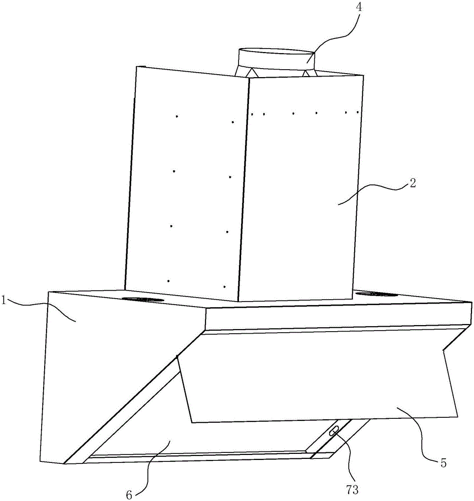
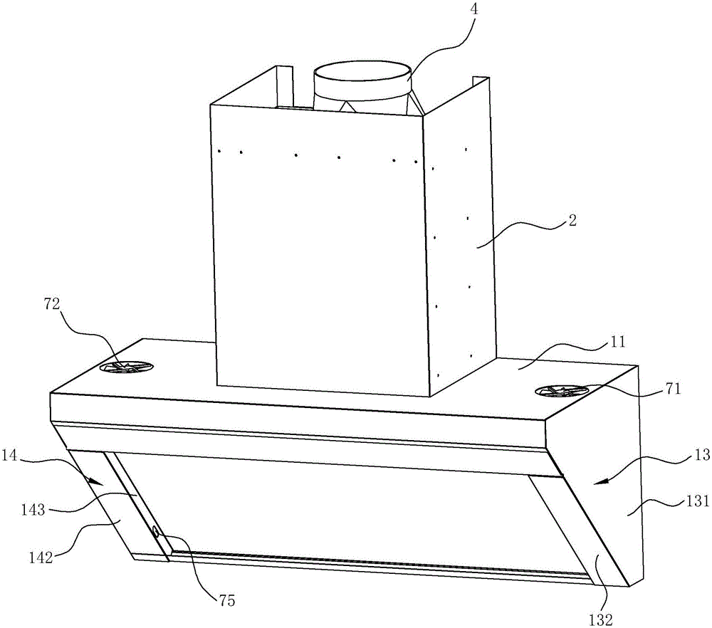
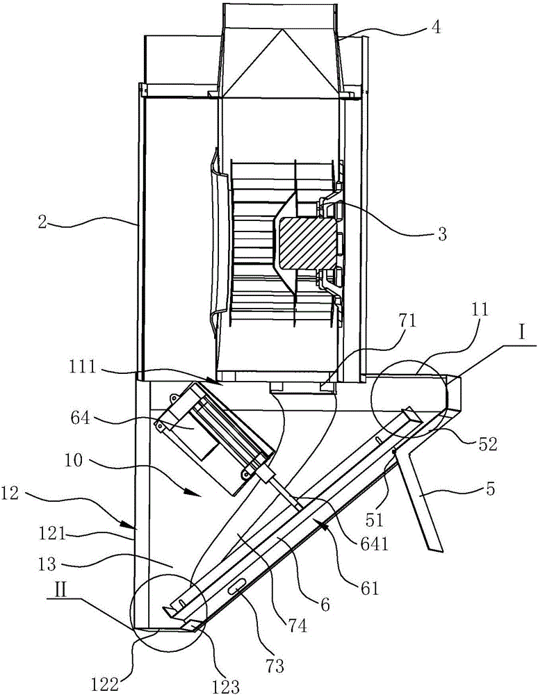
[0032] see Figure 1 ~ Figure 4 , an oil fume guiding type range hood, comprising a smoke collecting hood 1, and a fan cover 2 located above the smoke collecting hood 1, a fan 3 is arranged inside the fan cover 2, and is used to suck the oil fume into the range hood and pass it through the fan The air outlet cover 4 on the top of the cover 2 is discharged to the public flue.

[0033] For the convenience of description, "front", "rear", "left", and "right" below refer to the orientation of the range hood relative to the user when the range hood is in use. The shell of the fume collecting hood 1 includes a top plate 11 , a rear plate 12 , and a first side plate 13 and a second side plate 14 located on the left and right sides respectively. The back plate 12 is located at the back side of the top plate 11, the top of the back plate 12 is connected with the back side of the top plate 11, and the tops of the first side plate 13 and the second side plate 14 are respectively connect...

Embodiment 2

[0045] see Figure 9 and Figure 10 , in this embodiment, the difference from the first embodiment above is that the blower fan of the blowing and guiding device in the first embodiment sucks clean air from the outside of the range hood, while in this embodiment, the blowing and guiding device The device is arranged in the range hood, sucks the oil fume from the inside of the range hood and blows it out from the smoke guiding cavity 61 .

[0046] The first fan 71 and the second fan 72 are arranged on both sides of the smoke collecting chamber 10 , wherein the first fan 71 can be fixed to the first side plate 13 , and the second fan 72 can be fixed to the second side plate 14 . The first fan 71 is close to the first blowing port 73, and is connected to the first blowing port 73 through the first air guide 74, while the second fan 72 is close to the second blowing port 75, and is connected to the second blowing port 76 through the second wind guide 76. Air outlet 75. The firs...


PUM


Abstract

The invention discloses an oil fume guide type range hood which comprises a draught fan hood and a fume collecting hood. A draught fan is arranged inside the draught fan hood. A fume baffle is arranged on the upper portion of the front side of the fume collecting hood. The oil fume guide type range hood is characterized in that a fume guide plate is arranged on the rear side of the fume baffle; the space between the fume guide plate and the fume baffle forms a fume guide cavity; the space between the fume guide plate and the fume collecting hood forms a fume collecting cavity; further, clearances are reserved between at least two lateral sides of the fume guide plate and the position, corresponding to the fume collecting hood, of the shell, so that the fume guide cavity communicates with the fume collecting cavity; and the range hood further comprises an air blowing guide device which comprises air blowing ports, the air blowing ports are used for blowing out airflow which is close to the fume guide plate and flows obliquely upwards and towards the middle, and the air blowing ports are formed in the two sides of the front portion of the fume collecting hood correspondingly and close to the bottom of the fume collecting hood.

Description

technical field [0001] The invention relates to a range hood, in particular to a range hood with a fume guiding type. Background technique [0002] The traditional range hood is installed on the top of the cooker (top suction) or behind the side (side suction), and the cooking fume rises and diffuses naturally after it is generated. Commonly used side suction range hoods are usually provided with a casing and a smoke baffle arranged in front of the casing. Oil fume enters the casing from around the smoke baffle and then enters the air inlet of the range hood. [0003] For example, the Chinese patent application number 201220486226.3 discloses a range hood with an openable and closable air inlet, which includes a housing of the range hood. The air inlet is equipped with a smoke baffle that matches the shape of the air inlet. The upper end of the smoke baffle is hinged to the upper end of the air inlet through a hinge and can rotate around the hinge. The lower end of the smok...

Claims


Application Information

Patent Timeline
Patent Type & Authority Applications(China)
IPC IPC(8): F24C15/20
CPCF24C15/20F24C15/2071F24C15/2078
Inventor 李年平王军元贾博贤刘小祥茅忠群诸永定
Owner NINGBO FOTILE KITCHEN WARE CO LTD
Why Eureka
Try Eureka