Quantum imaging method and quantum imaging system

A technology of quantum imaging and measurement results, applied in optical components, instruments, optics, etc., can solve the problems of inability to realize, heavy storage load, large amount of calculation, etc., to improve the speed of data calculation, improve speed and efficiency, fast and efficient Imaging effect

Active Publication Date: 2016-11-23
北京坤煜量子科技有限责任公司
View PDF2 Cites 6 Cited by
  • Summary
  • Abstract
  • Description
  • Claims
  • Application Information

AI Technical Summary

Problems solved by technology

This makes the storage load of the system very heavy and cannot be implemented at the chip level. The current methods are all post-processing, that is, they are all stored in the computer system first, and then processed after the data is collected. This is to limit ghost imaging. A major obstacle for technology to be practical
[0004] Another way is to calculate To obtain images, although a large amount of data may not be stored, but because a large number of divisions are involved (equivalent to 640x480 images, each image needs to calculate 900,000 divisions), the calculation amount is very large and the speed is extremely slow. The data can only be stored in the computer system first, and then calculated offline
This also limits the practicality of ghost imaging techniques
[0005] To sum up, the current quantum imaging systems rely on computer systems for storage and cannot be used for online imaging, which greatly limits the real-time and practicality of the system.

Method used


Image

  • Quantum imaging method and quantum imaging system
  • Quantum imaging method and quantum imaging system
  • Quantum imaging method and quantum imaging system

Examples


Embodiment Construction

[0024] The present invention will be further elaborated below in conjunction with the accompanying drawings and embodiments, with reference to the accompanying drawings. It should be understood that these examples are only used to illustrate the present invention and are not intended to limit the scope of the present invention. In addition, it should be understood that after reading the content taught by the present invention, those skilled in the art can make various changes or modifications to the present invention, and these equivalent forms also fall within the scope defined by the appended claims of the present application.

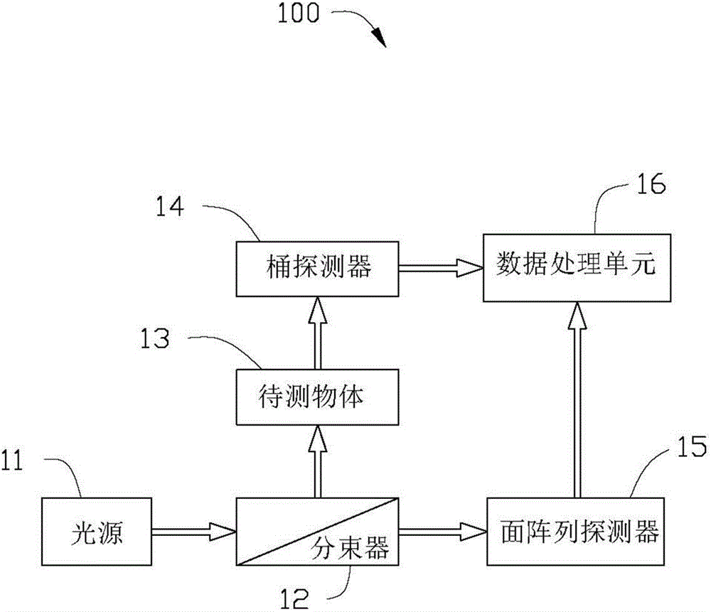
[0025] see figure 1 , the embodiment of the present invention provides a quantum imaging system 100 , which includes a light source 11 , a beam splitter 12 , a barrel detector 14 , a surface array detector 15 and a data processing unit 16 . The incident light emitted by the light source 11 enters the beam splitter 12 and is split into a signal light...


PUM


Abstract

The invention discloses a quantum imaging method and a quantum imaging system. The method comprises the following steps: S1) providing incident light; S2) splitting the incident light into signal light and reference light; S3) after the signal light irradiates an imaging object, collecting the light by a bucket detector and defining the nth measuring result as (SB)n; S4) collecting the reference light by a planar array detector, and defining the nth measuring result as (IR(x,y))n, wherein the (x,y) is pixel point coordinates corresponding to the planar array detector; and S5) storing the (SB)n and the (IR(x,y))n, and when receiving (n+1) data (SB)n+1 and the (IR(x,y))n+1, calculating g<~><2>(x)=<((SB)n+1- (SB)n)((IR(x,y))n+1-(IR(x,y))n)>.

Description

technical field [0001] The invention belongs to the field of quantum imaging, and the invention relates to an imaging method, in particular to a quantum imaging method and a quantum imaging system applying the quantum imaging method. Background technique [0002] Quantum imaging, also known as "ghost imaging" or "associated imaging", has made great progress in recent years and has attracted widespread attention. It has important theoretical and practical significance. Quantum imaging divides the light emitted by the light source (thermal light, pseudothermal light, etc.) Its total intensity, such as a large-area photodiode) is collected; another beam is called a reference light, which is directly irradiated on an area array detector (such as a CCD) (or a point detector is placed on a transverse plane at a suitable position in the reference light path) point scan). The result of each pixel on the area array detector and the result of the barrel detector are sent to the data...

Claims


Application Information

Patent Timeline
Patent Type & Authority Applications(China)
IPC IPC(8): G02B27/00G02B27/10
Inventor 李俊林杨哲龙桂鲁
Owner 北京坤煜量子科技有限责任公司
Why Eureka
Try Eureka