Recognition device

A recognition device and touch technology, applied in the electronic field, can solve problems such as slow trigger speed, high false trigger rate, and sensor work interference

Active Publication Date: 2016-11-23
SHANGHAI OXI TECH
View PDF6 Cites 11 Cited by
  • Summary
  • Abstract
  • Description
  • Claims
  • Application Information

AI Technical Summary

Problems solved by technology

[0003] However, when the current identification device is triggered and switched from the sleep state to the working state, there are generally problems of high false trigger rate and slow trigger speed.
[0004] At the same time, when the sensor is identifying, the parasitic capacitance generated by the identified object will interfere with the operation of the sensor

Method used


Image

  • Recognition device
  • Recognition device
  • Recognition device

Examples


Embodiment Construction

[0052] As mentioned above, when the current identification device is triggered to switch from the sleep state to the working state, there are generally problems of high false trigger rate and slow trigger speed.

[0053] At the same time, when the sensor performs identification, the parasitic capacitance formed between the user's finger and the identification sensor will interfere with the operation of the sensor.

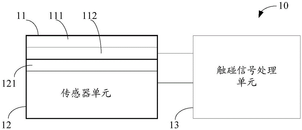
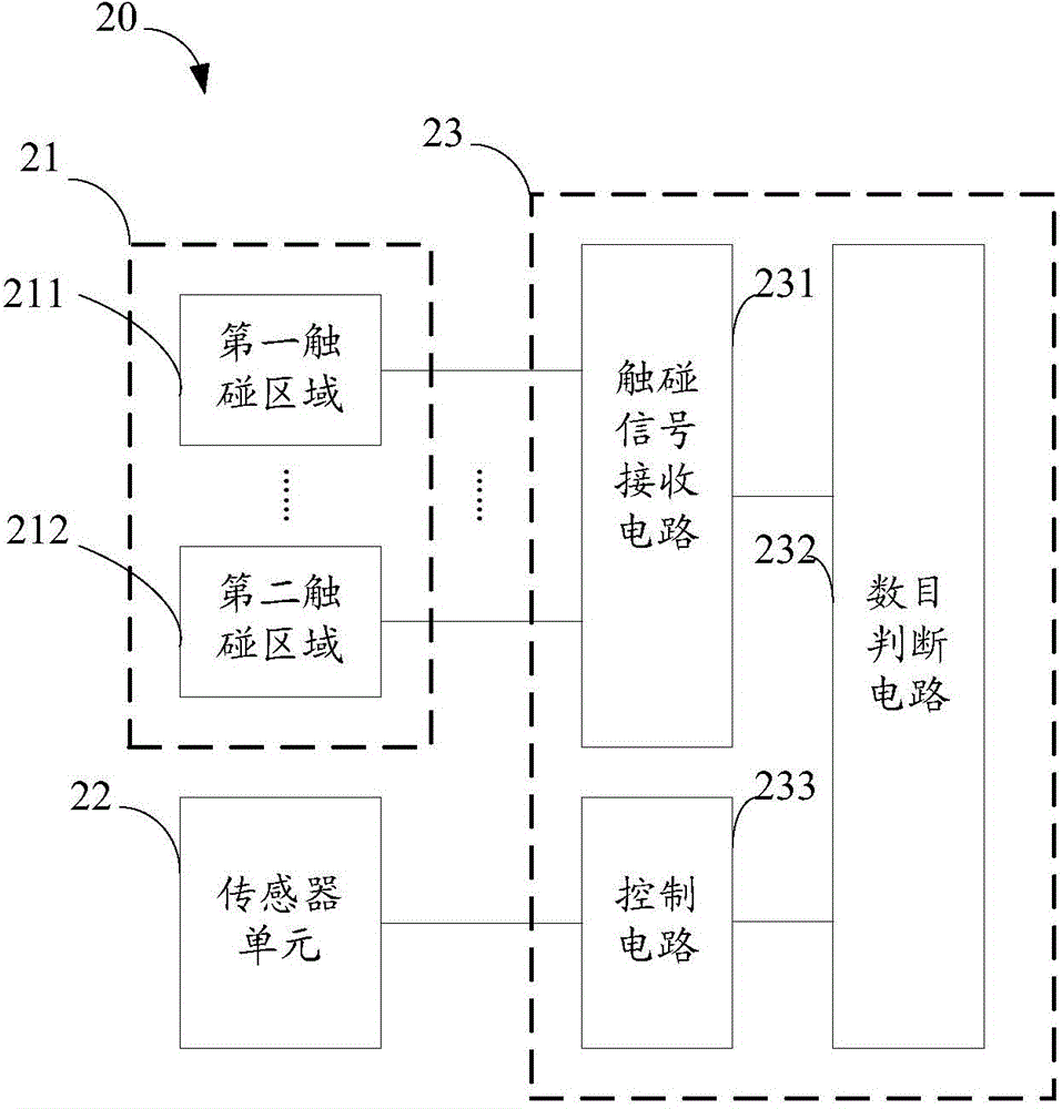
[0054] In the embodiment of the present invention, by setting the touch unit relative to the sensor unit, the working state of the sensor unit is controlled according to the number of touch areas in the touch unit where the capacitance or the amount of induced charge changes above a threshold value. The conductive layer between the sensor unit and the insulating layer shields the parasitic capacitance that interferes with the normal operation of the sensor unit, thereby improving the accuracy of identification. In addition, since the touch unit is arranged relative...


PUM


Abstract

The invention provides a recognition device. The recognition device comprises a touch unit, a touch signal processing unit and a sensor unit, wherein the touch unit is arranged relative to the sensor unit and comprises a conducting layer and an insulating layer; the conducting layer is arranged between the insulating layer and the sensor unit; the touch signal processing unit is coupled with the conducting layer of the touch unit; the touch unit comprises at least one touch region; the touch signal processing unit controls the working condition of the sensor unit according to the number of the touch regions with quantity change of capacitance above the threshold in the touch unit. The recognition device can rapidly switch the condition and improve the recognition accuracy.

Description

technical field [0001] The present invention relates to the field of electronic technology, in particular to an identification device. Background technique [0002] With the advancement of science and technology and the development of society, identification technology has become more and more widely used, especially biometric information identification technology, which has been widely used in various fields, such as access control, time attendance, and unlocking of electronic equipment. [0003] However, at present, when the identification device is triggered to switch from the sleep state to the working state, there are generally problems of high false trigger rate and slow trigger speed. [0004] At the same time, when the sensor is identifying, the parasitic capacitance generated by the object to be identified will interfere with the operation of the sensor. Contents of the invention [0005] The problem to be solved by the embodiments of the present invention is how...

Claims


Application Information

Patent Timeline
Patent Type & Authority Applications(China)
IPC IPC(8): G06F3/041G06F3/044G06K9/00
Inventor 郑娅洁凌严
Owner SHANGHAI OXI TECH
Why Eureka
Try Eureka