Double-power-source automatic transfer switching equipment

A technology of automatic transfer switch and dual power supply, which is applied to electric switches, power devices inside switches, circuits, etc., and can solve problems such as difficult rotation of the motor, slipping of the rotating arm and the shaft of the motor, and failure of the circuit breaker to move properly.

Active Publication Date: 2016-11-23
浙江万松电气有限公司
View PDF9 Cites 4 Cited by
  • Summary
  • Abstract
  • Description
  • Claims
  • Application Information

AI Technical Summary

Problems solved by technology

The dual power automatic transfer switch generally includes a motor. The shaft of the motor drives the automatic switching transmission device of the double circuit breaker switch to realize the conversion of the circuit breaker switch. A handle for manual driving is also set on the shaft. Once the motor fails, the handle can be used to drive the switch. For conversion work, since the handle is fixedly sleeved on the rotating shaft, the position of the rotating shaft in the motor is the rotor assembly. When the handle is driven, it is extremely laborious, which is not conducive to the convenience of operation.
[0003] And the double circuit breaker switch automatic switching transmission device is used to control two circuit breakers alternately on and off, the existing double circuit breaker switch automatic switching transmission device includes a fixed plate, and the fixed plate is provided with a motor, on the rotating shaft of the motor The sleeve is equipped with a rotating arm, and the two ends of the rotating arm are respectively hinged with a toggle seat, and the toggle seat is provided with an accommodating cavity for the switch of the circuit breaker. The motor drives the rotating arm to rotate to realize the switch on and off of the two circuit breakers. In this structure, slippage is likely to occur between the rotating arm and the motor shaft, and the motor is relatively difficult to rotate, which may easily cause the circuit breaker switch to not be turned on and off due to unstable work, posing a safety hazard

Method used


Image

  • Double-power-source automatic transfer switching equipment
  • Double-power-source automatic transfer switching equipment
  • Double-power-source automatic transfer switching equipment

Examples


Embodiment Construction

[0017] The present invention is specifically described below through examples, which are only used to further illustrate the present invention, and should not be construed as limiting the protection scope of the present invention.

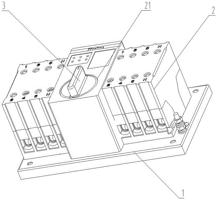
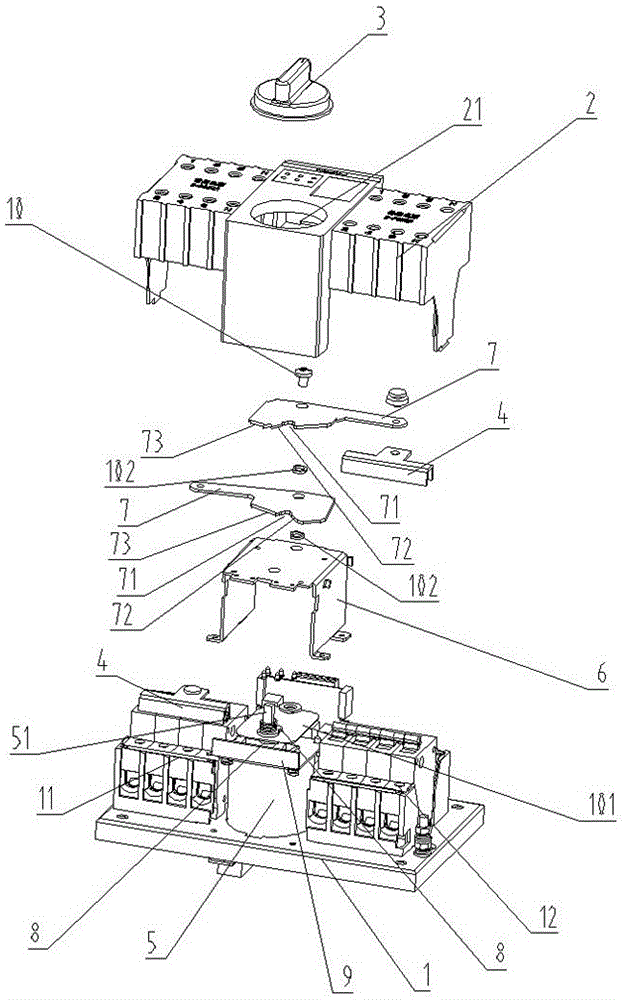
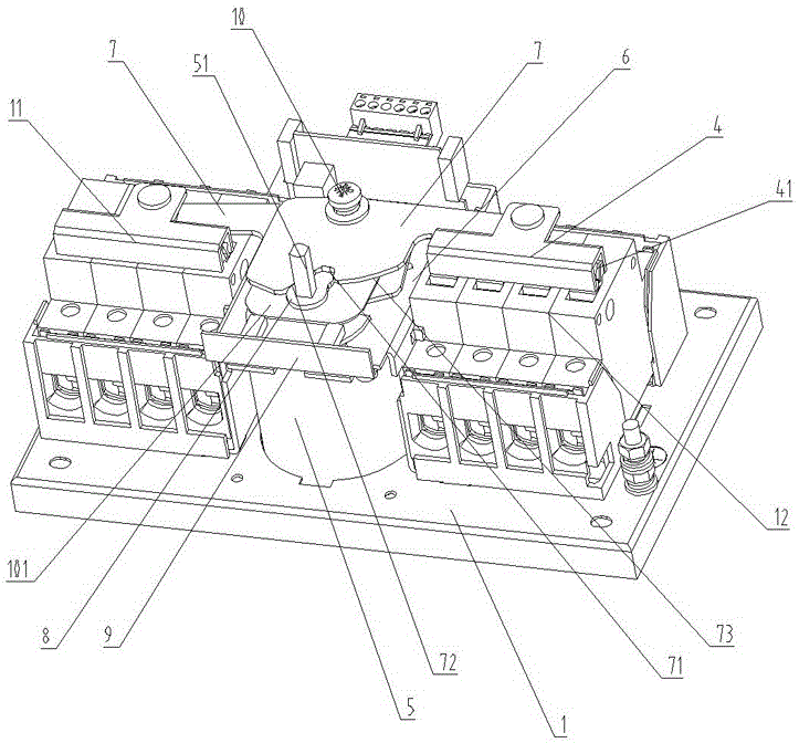
[0018] Such as figure 1 — Figure 4 As shown, this dual-power automatic transfer switch appliance includes a fixed base 1, an end cover 2 and a handle 3, and the two sides of the fixed base 1 are respectively provided with a main circuit breaker 11 connected to the normal power supply and a backup circuit breaker connected to the standby power supply. 12, the end cover 2 is provided with a handle groove 21 for the handle 3 to rotate and operate, and the top of the fixed seat 1 is provided with a toggle seat 4, and the toggle seat 4 is provided with an accommodating cavity 41 for placing a circuit breaker switch. The seat 1 is provided with a clutch motor 5, and the fixed seat 1 is provided with a mounting frame 6. The rotating shaft 51 on the clut...


PUM


Abstract

The invention discloses double-power-source automatic transfer switching equipment which comprises a fixing seat, an end cap and a handle. A main circuit breaker and a standby circuit breaker are arranged on two sides of the fixing seat respectively, a handle groove for allowing the handle to rotate is formed in the end cap, a stirring seat is arranged above the fixing seat, a clutch motor is arranged on the fixing seat, two transmission plates are hinged on a mounting frame, one ends of the transmission plates are hinged to the stirring seat, two cams in one-to-one correspondence to the transmission plates sleeve a rotating shaft of the clutch motor in a linkage manner, a driving groove matched with a driving end of the corresponding cam is formed in each transmission plate, one side of each driving groove outwards extends to form a concave-arc-shaped driving wall, the handle sleeves the end of the rotating shaft of the clutch motor, and after pressing the rotating shaft on the clutch motor, the handle can drive the rotating shaft to independently rotate movably. The double-power-source automatic transfer switching equipment has the advantages of being convenient and labor-saving in manual operation, stable and reliable in working and high in sensitivity.

Description

technical field [0001] The invention relates to the field of a circuit breaker, in particular to a dual power supply automatic transfer switching appliance. Background technique [0002] The purpose of the dual power automatic transfer switch is to put it simply as one common and one backup. When the common power suddenly fails or fails, it will be automatically switched to the backup power through the dual power switch. (The backup power can also be powered by a generator under small loads ,) to allow the device to still function normally. The dual power automatic transfer switch generally includes a motor. The shaft of the motor drives the automatic switching transmission device of the double circuit breaker switch to realize the conversion of the circuit breaker switch. A handle for manual driving is also set on the shaft. Once the motor fails, the handle can be used to drive the switch. Conversion work, because the handle is fixedly sleeved on the rotating shaft, the po...

Claims


Application Information

Patent Timeline
Patent Type & Authority Applications(China)
IPC IPC(8): H01H9/26H01H3/26
CPCH01H2300/018H01H9/26H01H3/26
Inventor 王重胜林一河
Owner 浙江万松电气有限公司
Why Eureka
Try Eureka