
Electrical connector

A technology of electrical connectors and power contacts, applied in the direction of connections, circuits, contact parts, etc., can solve problems such as incompatibility of data lines, achieve the effect of reducing manufacturing costs and improving compatibility

Active Publication Date: 2016-11-23
SHANGHAI TIANCHENG COMM TECH
View PDF7 Cites 2 Cited by
  • Summary
  • Abstract
  • Description
  • Claims
  • Application Information

AI Technical Summary

Problems solved by technology

However, the USB3.1 Type-C interface (including male and female ports) and data cables are not compatible with any existing types. If you need to be compatible with existing devices, you need to configure additional switching devices

Method used


Image

  • Electrical connector
  • Electrical connector
  • Electrical connector

Examples


Embodiment Construction

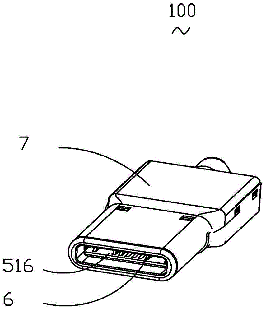
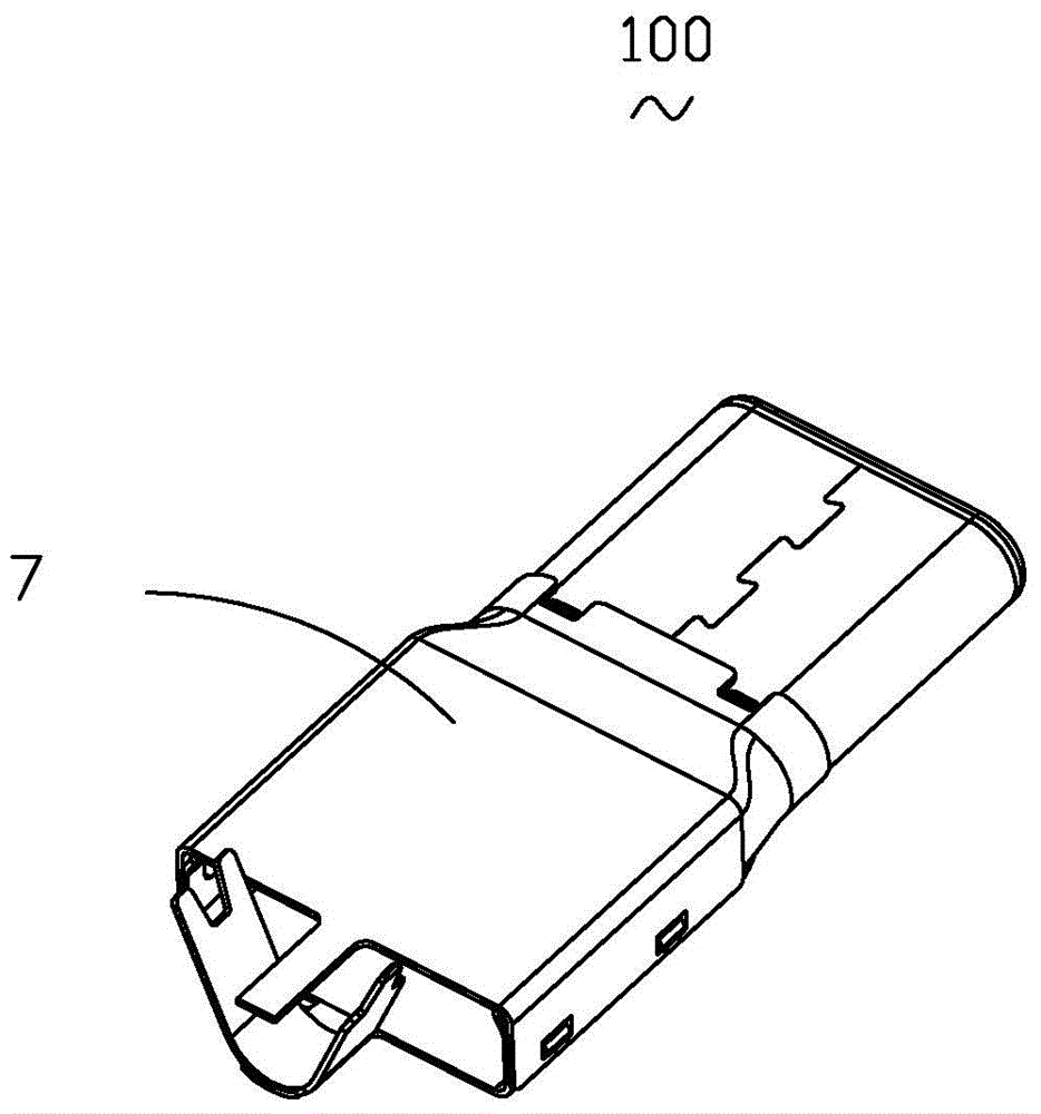
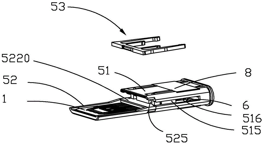
[0064] Please refer to Figures 1 to 10 As shown, the electrical connector 100 of the present invention is a USB2.0 electrical connector suitable for the interface frame of USB3.1 Type-C. The electrical connector 100 includes an insulating body 5, an electrical connector mounted on the insulating body 5 The connector terminal set 1 , the Mylar film 8 attached to the insulating body 5 , and the shielding case 7 shielding the outer side of the insulating body 5 .

[0065] Please refer to Figures 8 to 10 As shown, the electrical connector terminal set 1 is used to be fixed on the insulating body 5 of the electrical connector 100 . The electrical connector terminal set 1 includes several conductive terminals 6, the conductive terminals 6 include head portions 31, 41 and tail portions 32, 42 connecting the head portions 31, 41, and the head portions 31, 41 are provided with electrical To connect the contacts of the mating connector (not shown), the tails 32 and 42 of the differe...


PUM


Abstract

The invention discloses an electrical connector. The electrical connector includes an insulation body and an electrical connector terminal group; the electrical connector terminal group include a first row of contacts and a second row of contacts; the first row of contacts sequentially comprises a first grounding contact, a first power source contact, a signal sending contact, a signal receiving contact, a first detecting contact, a second power source contact and a second grounding contact; the second row of contacts sequentially comprises a third grounding contact, a third power source contact, a second detecting contact, a fourth power source contact and a fourth grounding contact; the first grounding contact and the third grounding contact are opposite to each other in a vertical direction; the first power source contact and the third power source contact are opposite to each other in a vertical direction; the second grounding contact and the fourth grounding contact are opposite to each other in a vertical direction; the second power source contact and the fourth power source contact are opposite to each other in a vertical direction; the first detecting contact and the second detecting contact are distributed at two sides of the signal sending contact and the signal receiving contact in a left-and-right direction; the insulation body is provided with an accommodating cavity and terminal accommodating grooves; and the contacts are exposed in the accommodating cavity. Thus, the electrical connector has high compatibility and is low in cost.

Description

technical field [0001] The invention relates to an electrical connector, in particular to an electrical connector with several conductive terminals. Background technique [0002] The biggest feature of USB3.1 Type-C is that although the size of the opening is as small as the standard Micro-B connector for Android smartphones and tablet computers, it supports a maximum data transmission speed of 10G bit / s. The opening size of the Type-C jack is about 8.3mm×2.5mm (Micro-B is about 7.5mm×2.5mm). It can withstand 10,000 insertions and withdrawals reaching the level of connector products. In addition, Type-C also supports the "USB Power Delivery Specification (USB PD)" which improves the power supply capability compared with the past. According to the available power, USB PD has five levels of specifications: 10W, 18W, 36W, 60W, and 100W. The Type-C connector supports 100W (20V, 5A) power supply. [0003] USB3.1Type-C has also taken many measures to improve ease of use. For ...

Claims


Application Information

Patent Timeline
Patent Type & Authority Applications(China)
IPC IPC(8): H01R27/00H01R13/02
Inventor 熊峰
Owner SHANGHAI TIANCHENG COMM TECH
Learn More