
Electromagnetic-resonance wireless charging device

An electromagnetic resonance and wireless charging technology, which is applied in the direction of battery circuit devices, circuit devices, current collectors, etc., can solve the problems of limited use range, temperature rise, and short wireless transmission distance, so as to ensure service life, normal operation, and charging long distance effect

Inactive Publication Date: 2016-11-23
TEN PAO ELECTRONICS HUIZHOU +1
View PDF4 Cites 2 Cited by
  • Summary
  • Abstract
  • Description
  • Claims
  • Application Information

AI Technical Summary

Problems solved by technology

[0002] At present, electromagnetic induction wireless chargers are widely used in the market. Not only the wireless transmission distance is short, but also the charging terminal needs to be aligned with the wireless charger to charge normally, and the scope of use is greatly limited; When the magnetic induction wireless charger is charged in contact, not only the efficiency of the charger is low, but also the heat generated by the wireless transmitting coil and the wireless receiving coil cannot be dissipated in a timely and effective manner, resulting in an increase in the temperature of charging terminals such as mobile phones, tablet computers and other portable devices. The aging of components, especially the battery of the charging terminal, will seriously shorten the life of the battery
[0003] In addition, during the charging process of the electromagnetic induction wireless charger, the user can hardly use the charging terminal, which will greatly affect the handling of emergency matters, let alone long-term games and entertainment, which will bring great inconvenience to the user; and the charging The charger and charging terminal generally work in a static state. If they are in a bumpy environment such as a car or a boat, they cannot be charged or the charging effect is not good.

Method used


Image

  • Electromagnetic-resonance wireless charging device
  • Electromagnetic-resonance wireless charging device
  • Electromagnetic-resonance wireless charging device

Examples


Embodiment Construction

[0020] The following will clearly and completely describe the technical solutions in the embodiments of the present invention with reference to the drawings in the embodiments of the present invention. The following descriptions are only preferred embodiments, and do not constitute a limitation to the protection scope of the present invention.

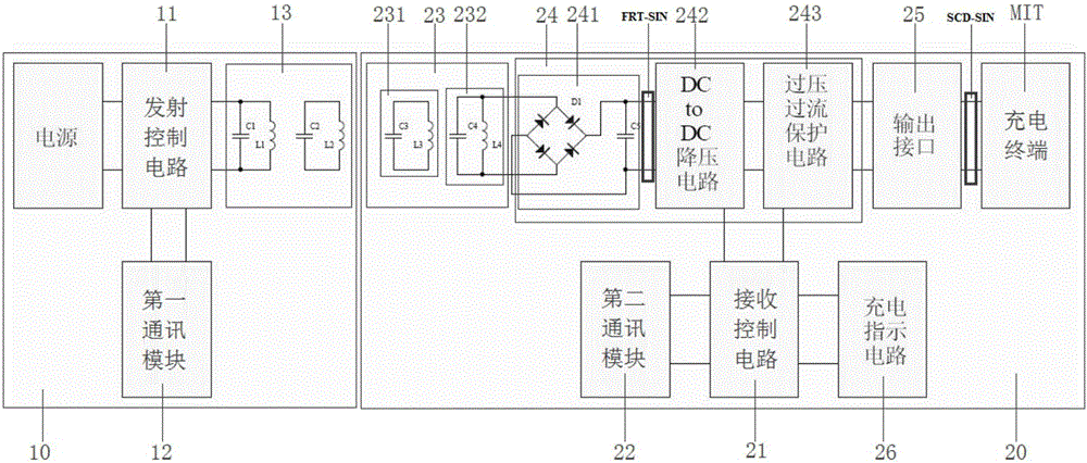
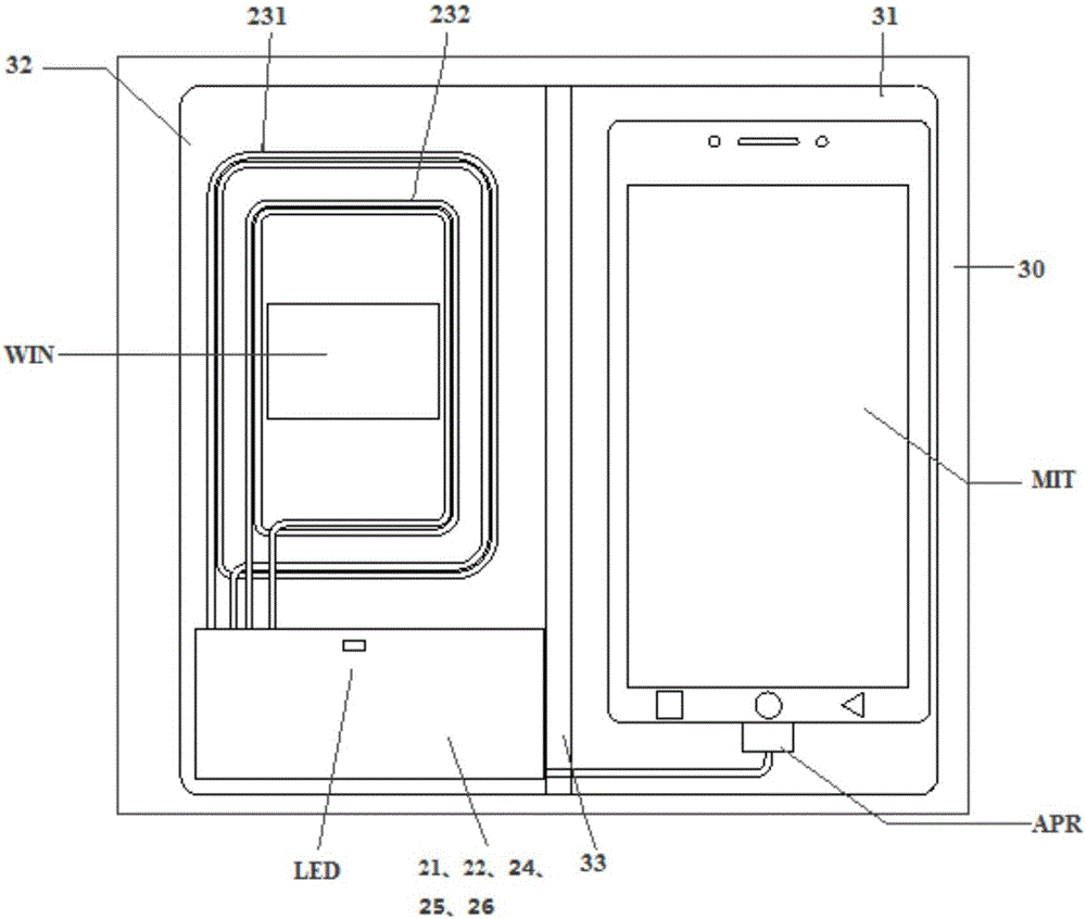
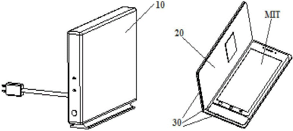
[0021] see figure 1 , is a specific circuit schematic diagram of an electromagnetic resonance wireless charging device provided by the present invention. In this embodiment, the electromagnetic resonance wireless charging device includes a power supply wireless transmitting unit 10, and the power supply wireless transmitting unit includes a transmission control circuit 11, a first communication module 12 connected thereto, and a wireless transmitting coil 13, The wireless transmitting coil 13 transmits a power supply wireless signal.

[0022] The power supply wireless receiving and charging control unit 20 is provided with a receivin...


PUM


Abstract

The invention provides an electromagnetic-resonance wireless charging device which comprises a power supply wireless transmitting unit. The electromagnetic-resonance wireless charging device further comprises a power supply wireless receiving and charging control unit and a flip type structure used for fixing the power supply wireless receiving and charging control unit and being connected with a charging terminal; the power supply wireless receiving and charging control unit is provided with a receiving control circuit and a second communication module, a wireless receiving coil and a resonance loading coil which are connected with the receiving control circuit, the wireless receiving coil receives a power supply wireless signal, the power supply wireless signal is converted into a first power supply signal through the resonance loading coil, a second power supply signal is output by a power supply output interface after the first power supply signal is rectified, subjected to voltage decreasing and adjusted by a protection circuit, and then the charging terminal is charged. According to the electromagnetic-resonance wireless charging device, the power supply wireless receiving and charging control unit and the flip type structure are adopted, the charging range is wide, the anti-jamming capability is high, and the heat dissipation speed is high; in addition, the charging terminal can be charged in a waggling and jolting environment.

Description

technical field [0001] The invention relates to the technical field of wireless charging, in particular to an electromagnetic resonance wireless charging device. Background technique [0002] At present, electromagnetic induction wireless chargers are widely used in the market. Not only the wireless transmission distance is short, but also the charging terminal needs to be aligned with the wireless charger to charge normally, and the scope of use is greatly limited; When the magnetic induction wireless charger is charged in contact, not only the efficiency of the charger is low, but also the heat generated by the wireless transmitting coil and the wireless receiving coil cannot be dissipated in a timely and effective manner, resulting in an increase in the temperature of charging terminals such as mobile phones, tablet computers and other portable devices. The aging of the components, especially the battery of the charging terminal, will seriously shorten the life of the bat...

Claims


Application Information

Patent Timeline
IPC IPC(8): H02J7/00H02J50/20
CPCH02J7/025
Inventor 严崇俊朱昌亚洪光岱
Owner TEN PAO ELECTRONICS HUIZHOU
Learn More