Control method, control server and control system

A technology for controlling servers and control systems, applied in transmission systems, electrical components, etc., can solve security problems, performance degradation of user equipment, infringement of user equipment, etc., to reduce workload, facilitate access and control, and reduce security risks. Effect

Inactive Publication Date: 2016-11-23
KORTIDE LTD
4 Cites 0 Cited by

AI-Extracted Technical Summary

Problems solved by technology

Poorly developed applications can lead to overall performance degradation on user devices such as smartphones and tablets
Some mal...

Abstract

The present invention relates to a control method, a control server and a control system. The control server comprises: a communication unit configured to receive description information from a device to be controlled, wherein the control description information is configured to describe the control mode of the device to be controlled; a control unit configured to analyze the control description information received by the communication unit; and a service providing unit configured to provide analyzed control description information to a third party application, wherein the control information is input through the analyzed control description information through the third party application, and the communication unit sends the input control information to the device to be controlled.

Application Domain

Transmission

Technology Topic

Embedded systemInput control +6

Image

  • Control method, control server and control system
  • Control method, control server and control system
  • Control method, control server and control system

Examples

  • Experimental program(1)

Example Embodiment

[0032] Hereinafter, embodiments of the present disclosure will be described in detail with reference to the accompanying drawings. However, the present invention may be embodied in many different forms and should not be construed as limited to the embodiments set forth herein. These embodiments are provided so that this disclosure will be thorough and complete, and will fully convey the scope of the invention to those skilled in the art. In the drawings, for the sake of clarity, various components have not been drawn to scale, and the same reference numbers will be used throughout to refer to the same or like components.
[0033] The terms "a," "an," and "the" and similar referents when used in the context of describing the present invention should be construed to encompass both the singular and the plural unless otherwise specified or clearly indicated by the context. The terms "including," "having," "including," and "containing" should be construed as open-ended terms (ie, meaning "including, but not limited to,") unless otherwise indicated.
[0034] Unless otherwise defined, all technical and scientific terms used herein have the same meaning as commonly understood by one of ordinary skill in the art to which this invention belongs. It should also be understood that any and all examples or exemplary terms used herein are used only to better clarify the invention and not to limit the scope of the invention, unless otherwise indicated. Also, all terms defined in commonly used dictionaries should not be unduly construed unless otherwise defined.
[0035] [controlling device]
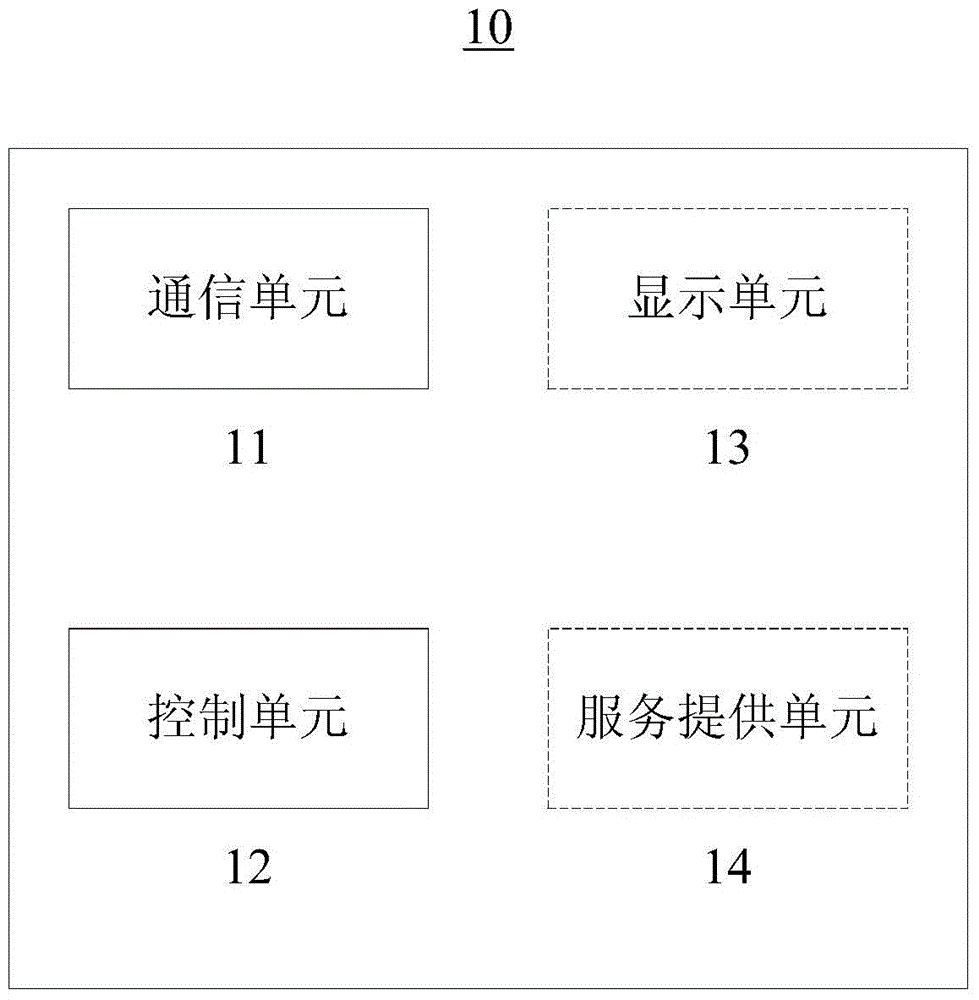
[0036] figure 1 A schematic block diagram of a control device according to an embodiment of the inventive concept is shown.
[0037] like figure 1 As shown, the control device 10 according to an embodiment of the present inventive concept may include a communication unit 11 and a control unit 12 . The communication unit 11 is used for receiving control description information from the device to be controlled. The control unit 12 is used for parsing the control description information received by the communication unit 11 . Control information is input according to the parsed control description information, and the communication unit 11 transmits the input control information to the device to be controlled.
[0038] According to an embodiment of the inventive concept, the control device may be implemented as a controller. In this case, the control device may include a display unit 13 for displaying the control interface. A control interface corresponding to the received control description information may be displayed on the display unit 13 according to the parsed control description information. The user can input control information through the displayed control interface.
[0039] According to another embodiment of the inventive concept, the control device may be implemented as a control server. In this case, the control device may include a service providing unit 14 that provides the parsed control description information to a third-party application. Control information can be input according to the parsed control description information through a third-party application.
[0040] According to yet another embodiment of the inventive concept, the control device may be implemented as a control device having both the display unit 13 and the service providing unit 14 . Therefore, a control interface corresponding to the received control description information can be displayed on the display unit 13 according to the parsed control description information. The user can input control information through the displayed control interface. In addition, the parsed control description information can also be provided to a third-party application, and the control information can be input according to the parsed control description information through the third-party application.
[0041] The control description information may include one or more of the following: control type, control word corresponding to the control, display position corresponding to the control, display information corresponding to the control, bitmap corresponding to the control, and description corresponding to the control information. However, the present invention is not limited thereto, and the control description information may include any information used to describe the control mode of the device to be controlled, or may also include any information used to display a control interface.
[0042] [controller]
[0043] The following will refer to figure 2 and image 3 An embodiment in which the control device is implemented as a controller having the display unit 13 will be described.
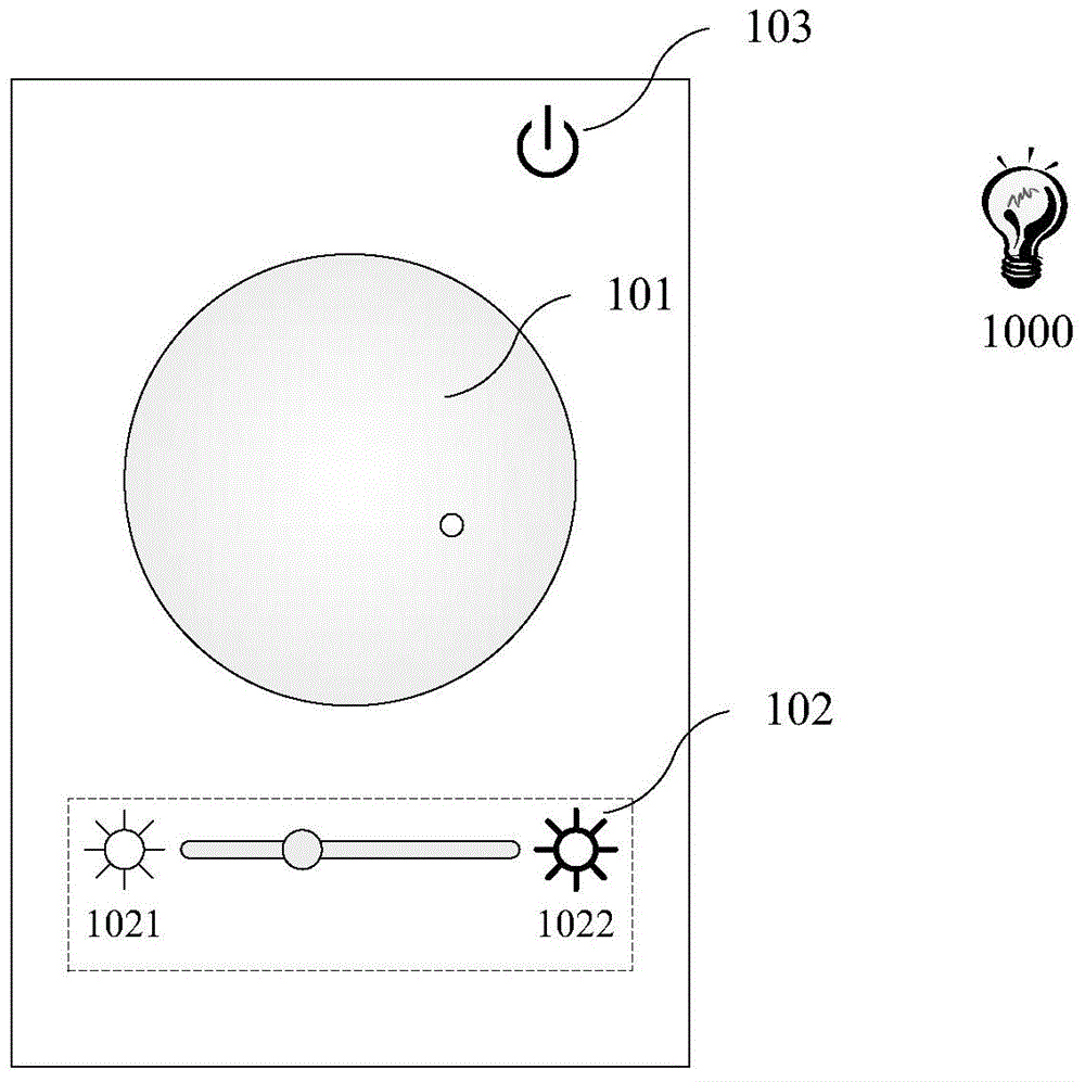
[0044] figure 2 The display unit 13 of the control device (controller) 10 according to the parsed control description information is exemplarily shown Place An example of the displayed control interface. figure 2 The illustrated example of a control interface may be used to control the smart light bulb 1000 . That is, it is displayed based on the result of parsing the control description information obtained from the smart light bulb 1000 (ie, the device to be controlled) figure 2 control interface shown.
[0045] refer to figure 2 , the control interface for controlling the smart light bulb 1000 may include, for example, three controls: a color selection control 101 , a brightness selection control 102 and a switch control 103 .
[0046] exist figure 2 In the example shown, the color selection control 101 can be a circular hue diagram, and the user can control the color of the light emitted by the smart light bulb 1000 through the color selection control 101 . Brightness selection control 102 may be a bar-type control and includes icons 1021 and 1022 indicating low brightness and high brightness, respectively. The user can control the brightness of the smart light bulb 1000 by sliding on the brightness selection control 102 or clicking the corresponding position of the bar-type control. The switch control 103 can be a button-type control. figure 2 In the example shown, the switch control 103 is displayed as a commonly used switch icon. The user can turn the smart light bulb 1000 on or off by clicking the switch control 103 .
[0047] It should be recognized that figure 2 The control interface that can be displayed according to the result of parsing the control description information is shown by way of example only, but the present invention is not limited thereto.
[0048] According to an embodiment of the present inventive concept, the communication unit 11 of the control device 10 may receive data packets from the device to be controlled and parse the received data packets by the control unit 12 . In addition, the content corresponding to the received data packet may also be displayed on the control interface displayed by the display unit 13 of the control device 10 . Alternatively or additionally, the control unit 12 of the control device 10 may process the parsed data packets and send the processed data packets to the device to be controlled via the communication unit 11 .
[0049] The data packets received from the device to be controlled may include one or more of the following: static image data packets, dynamic image data packets, audio data packets, video data packets, data packets representing human vital signs, data representing environmental parameters packet, a data packet representing the parameters of the device to be controlled, but the present invention is not limited to this.
[0050] It should be appreciated that various custom types of data packets may exist on the device to be controlled, and the control device does not know the type or data format of the data packets in advance. In this case, the control device may receive a data template for parsing the data packet from the device to be controlled. According to an embodiment of the inventive concept, the data packet may be transmitted from the device to be controlled to the control device together with the data template. For example, the data types used to provide the data packets are data types with self-describing information and/or metadata. According to another embodiment of the present invention, when the control device fails to parse the data packet received from the device to be controlled, the control device may send a request to the device to be controlled to obtain a corresponding data template.
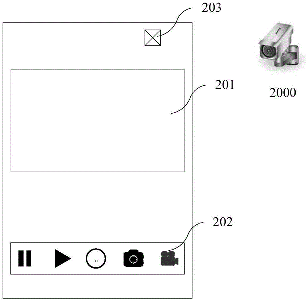
[0051] image 3 Another example of a control interface displayed by the display unit 13 of the control device (controller) 10 according to the parsed control description information is exemplarily shown. image 3 The example of the control interface shown is for controlling the webcam 2000 . That is, it is displayed based on the result of parsing the control description information obtained from the network camera 2000 (ie, the device to be controlled) image 3 control interface shown.
[0052] refer to image 3 , the control interface for controlling the IP camera 2000 may include, for example, three controls: a window control 201 , a button group control 202 and a switch control 203 .
[0053] exist image 3 In the example shown, the window control 201 is a rectangular window, and the user can watch the real-time dynamic picture transmitted by the network camera 2000 to the control device 10 through the window control 201 . The control device 10 parses the data packets transmitted from the network camera 2000 to display a real-time dynamic picture in the window control 201 . In addition, the user can also control the network camera 2000 by touching different parts of the window control 201 . For example, the user can make the webcam 2000 deflect accordingly by touching the edge part of the window control 201 or a single-finger sliding gesture; Push and pull the lens.
[0054] The button group control 202 integrates multiple buttons, eg, play, pause, capture or record, and so on. Furthermore, in image 3 In the example shown, the button group control 202 also integrates an extension button (that is, the button in the middle of the button group control 202), and the user can click the extension button to make the control interface display more buttons, so as to control the network camera 2000 or Process the displayed content.
[0055] switch control 203 in image 3 The example shown is an "X" shaped icon. The user can turn on or off the IP camera 2000 by clicking the switch control 203 . It should be recognized that in figure 2 and image 3 In the example of the control interface, the switch controls 103 and 203 with the same function are respectively included, but the icons of the switch controls 103 and 203 are different. This is because, in the control description information provided by the smart light bulb 1000 and the network camera 2000, different bitmap or picture resources for displaying the switch controls 103 and 203 are respectively provided.
[0056] exist image 3 In the example shown, the content corresponding to the data packet received from the device to be controlled, that is, the real-time dynamic picture, can be displayed on the control interface. According to another embodiment of the present inventive concept, after the control unit 12 of the control device 10 parses the data packets received from the device to be controlled, the control unit 12 may also process the parsed data packets, and send the data packets to the communication unit 11 through the communication unit 11 . The processed data packets are sent to the device to be controlled.
[0057] It should be recognized that figure 2 and image 3 The smart light bulb 1000 and the web camera 2000 are shown as devices to be controlled by way of example only, but the present invention is not limited thereto.
[0058] The control device according to the inventive concept may be a controller with an entity, or may be an application program installed on the user equipment. refer to figure 2 and image 3 The implementation of the control device according to the inventive concept as a controller having a display unit is described. Furthermore, the control device according to the present inventive concept can also be implemented as an application program capable of running on a user device (eg, a smartphone or a tablet computer) having a display unit. That is, the control device according to the present inventive concept can be implemented in software, and when the software is run on a user device such as a smart phone or a tablet, the user device can be used as a device to be controlled. control controller.
[0059] [control server]
[0060] The following will refer to Figure 4 and Figure 5 An embodiment in which the control device is implemented as a control server having the service providing unit 14 will be described.
[0061] Figure 4 and Figure 5 A third-party application is exemplarily shown, and the third-party application can control the device to be controlled using the parsed control description information provided by the control server according to the embodiment of the present inventive concept.
[0062] like Figure 4 As shown, the third-party application may be a camera application 3000 running on a user device such as a smartphone or tablet. When the camera application 3000 is executed to prepare for taking a picture or a video, the user can set shooting parameters such as color temperature through a setting interface provided by the camera application 3000 . At this time, the camera application 3000 may issue a request to the control server according to the present embodiment to obtain the parsed control description information of, for example, the smart light bulb 1000 installed in the photographing environment.
[0063] According to the control server of the present embodiment, the communication unit 11 receives the control description information for describing the control mode of the device to be controlled from the device to be controlled, the control unit 12 parses the control description information received by the communication unit, and the service The providing unit 14 then provides the parsed control description information to the requesting third-party application.
[0064] The control description information may include any information used to describe the control manner of the device to be controlled, or may also include any information used to display a control interface. For the control server, it is only necessary to provide the third-party application with information describing the control mode of the device to be controlled.
[0065] The third-party application that has obtained the parsed control description information can input the control information. For example, the camera application 3000 may input the color temperature set by the user as control information to the control server according to the present embodiment. Subsequently, the communication unit 11 transmits the input control information to the device to be controlled. For example, the color temperature set by the user is sent to the smart light bulb 1000 as control information, so as to provide a shooting environment consistent with the shooting parameters set by the user.
[0066] also, Figure 5 It is schematically shown that the camera application 3000 can obtain data packets provided by, for example, the network camera 2000 by making a request to the control server according to the present embodiment.
[0067] According to the control server of this embodiment, the communication unit 11 can receive data packets from the device to be controlled, the control unit 12 parses the received data packets, and the service providing unit 14 provides the parsed data packets to the requesting third-party application .
[0068] Similar to the above-mentioned embodiment of the controller, the data packets received from the device to be controlled may include one or more of the following: static image data packets, dynamic image data packets, audio data packets, video data packets, physical signs representing body signs Data packets of parameters, data packets of environment parameters, and data packets of parameters of the device to be controlled itself, but the present invention is not limited to this.
[0069] In addition, the control server according to this embodiment may receive a data template for parsing the data packet from the device to be controlled. The manner of receiving the data template is similar to that of the above-mentioned embodiment of the controller, and thus the description will not be repeated.
[0070] Third-party applications can display or utilize content corresponding to received packets. E.g, Figure 5 The illustrated camera application 3000 can display the real-time dynamic picture of the network camera 2000, and use the network camera 2000 to take pictures or video. Alternatively or additionally, the third-party application may process the parsed data packet and send the processed data packet to the device to be controlled via the communication unit 11 of the control server.
[0071] It should be recognized that Figure 4 and Figure 5 By way of example only, the camera application 3000 is shown as a third party capable of controlling the devices to be controlled (eg, the smart light bulb 1000 and the web camera 2000 ) using the parsed control description information provided by the control server according to the present inventive concept application, but the present invention is not limited to this.
[0072] The control server according to the inventive concept may be a server with an entity, or may be a control service program installed on the user equipment. When the control server according to the present invention is implemented in the form of a control service program, various third-party applications on the user equipment running the control service program can conveniently access and control the device to be controlled through the control service program.
[0073] [Control System]
[0074] A control device according to an embodiment of the inventive concept (eg, figure 1 The control device 10 shown) and the device to be controlled (eg, figure 2 and image 3 The illustrated smart light bulb 1000 and network camera 2000) constitute a control system according to an embodiment of the inventive concept. The device to be controlled sends the control description information to the control device, and the control device parses the received control description information. Control information is input according to the parsed control description information, and the control device sends the input control information to the device to be controlled.
[0075] The control device may be implemented as a controller having a display unit, or may be implemented as a control server having a service providing unit. Regardless of the manner in which the control device according to the present inventive concept is implemented, it can be used to constitute a control system according to the present inventive concept.
[0076] When the control device is implemented as a controller with a display unit, the control device can display a control interface corresponding to the received control description information according to the parsed control description information, and input control information through the displayed control interface. In addition, the control device can receive data packets from the device to be controlled and parse the received data packets. The control device may display content corresponding to the received data packets on the control interface. Alternatively or additionally, the control device may process the parsed data packets and send the processed data packets to the device to be controlled.
[0077] When the control device is implemented as a control server with a service providing unit, the device to be controlled sends the control description information to the control server, and the control server parses the received control description information, and provides the parsed control description information to a third-party application . Control information is input according to the parsed control description information through a third-party application, and the control server sends the input control information to the device to be controlled. In addition, the control server can receive data packets from the device to be controlled and parse the received data packets, and the control server can provide the parsed data packets to a third-party application. Third-party applications can display or utilize content corresponding to received packets. Alternatively or additionally, the third-party application may process the parsed data packets and send the processed data packets to the device to be controlled via the control server.
[0078] According to an embodiment of the inventive concept, a control device (a controller or a control server) may periodically (or manually by a user) search for a device to be controlled, and send a control access request to the searched device to be controlled. After receiving the control access request sent by the control device, the device to be controlled can respond to allow or deny the control access request from the control device. Only after receiving a response signal indicating that access and control of the device to be controlled is permitted, the control device can establish a control connection with the device to be controlled. As used herein, a "controlling connection" refers to a connection through which the controlling device can control the device to be controlled.
[0079] While sending the control access request to the searched device to be controlled, or after sending the control access request, the control device may send identity authentication information to the searched device to be controlled. After confirming that the received identity authentication information is valid identity authentication information, the device to be controlled can send a response signal allowing access and control; after confirming that the received identity authentication information is invalid identity authentication information, the device to be controlled can Send a rejection signal.
[0080] Taking the control device implemented as a controller with a display unit as an example, Figure 6A and Figure 6B A schematic diagram showing a plurality of devices to be controlled displayed on the display unit of the control device is shown. exist Figure 6A In the schematic diagram shown, three devices to be controlled are shown: a camera 1 located in the object, a camera 2 located in the study, and a light bulb 1 located in the object. exist Figure 6B In the schematic shown, a light bulb 2 located in the kitchen has been added. Below with Figure 6A and Figure 6B Taking the situation shown as an example, the process of discovering and adding a device to be controlled by the control device will be described.
[0081] For example, when the control device searches for the light bulb 2 located in the kitchen, an icon representing the light bulb 2 may be displayed on the display unit, such as Figure 6B shown. The user can then click on the icon representing the light bulb 2 to establish a control connection with the light bulb 2 . Before establishing a control connection, a user name and password may be prompted for authentication information representing the user's identity. The initial authentication information can be printed on the device to be controlled (or its packaging). After the control connection is established for the first time, the user name and password can be modified, or new valid authentication information can be added for the device to be controlled (ie, a new user is added).
[0082] When the control device is implemented as a control server having a service providing unit, the process of adding the device to be controlled may be without user participation. Before establishing the control connection, the control server can automatically provide the identity authentication information to the device to be controlled. However, the present invention is not limited thereto, and the control server according to the present inventive concept may also include the display unit 13, and may operate in a manner similar to the reference Figure 6A and Figure 6B Add the device to be controlled in the way described.
[0083] Figure 7A and Figure 7B A schematic diagram of a control system according to an embodiment of the inventive concept is shown. exist Figure 7A In the example of the control system shown, the control device is shown as a controller with a display unit, in Figure 7B In the example of the control system shown, the control device is shown as a control server with a service providing unit.
[0084] exist Figure 7A and Figure 7B In the control system shown, in addition to the control device and the device to be controlled, a registration server is also included. The registration server is used to register/deregister the device to be controlled. The control device can access the registration server to search for the device to be controlled according to the registration status of the device to be controlled in the registration server. However, the registration server is not necessary, and the control device can search for the device to be controlled by itself.
[0085] again with Figure 6A and Figure 6B In the case shown as an example, after the light bulb 2 located in the kitchen has been registered on the registration server, the control device can search for the registered light bulb 2 when accessing the registration server, and can display the light bulb 2 on the display unit 13. icon, such as Figure 6B shown. The user can then click on the icon representing the light bulb 2 to establish a control connection with the light bulb 2 . Alternatively or additionally, the control server may automatically add bulbs 2 and establish a control connection with bulbs 2 .
[0086]When the device to be controlled is activated, the registration server registers the activated device to be controlled, and when the device to be controlled is closed, the registration server deregisters the closed device to be controlled. For example, during the startup process of the device to be controlled, the device to be controlled may perform a registration operation in the registration server, and the registration server registers the device to be controlled as an activated state. Furthermore, the registration server may record the control devices to which access is made, and send a notification to the recorded control devices when registering and/or deregistering the device to be controlled. For example, the control device searches for the device to be controlled through the registration server (for example, Figure 6B bulb 2 shown), and a control connection is established with bulb 2. After the light bulb 2 is deregistered from the registration server, the registration server may send a notification that the light bulb 2 has been deregistered to the control device, and when the light bulb 2 is registered on the registration server again, send a notification that the light bulb 2 has been registered to the control device. The control device may be a controller with a display unit or a control server with a service providing unit.
[0087] According to an embodiment of the present inventive concept, the device to be controlled can autonomously perform registration/deregistration operations on the registration server. For example, when the device to be controlled is started, it may not register on the registration server, but when a certain condition is satisfied, the device to be controlled autonomously performs a registration operation on the registration server, and when the specific condition is no longer satisfied, the device to be controlled is no longer satisfied. The control device autonomously performs a logout operation on the registration server. The specific conditions include (but are not limited to) the environment where the device to be controlled is located, the state of the device to be controlled, a predetermined time period, and the like.
[0088] In the case where the control device searches for registered devices to be controlled only by accessing the registration server, the control device cannot know the devices to be controlled that are activated but not yet registered. The control device may send a request to the registration server to search for devices to be controlled that have been activated but not yet registered. If the registration server searches for a device to be controlled that is activated but not yet registered, and the device to be controlled once established a controlling connection with the requesting control device, the registration server can "push" the searched device to be controlled to the control device equipment. The control device may be a controller with a display unit or a control server with a service providing unit.
[0089] According to an embodiment of the inventive concept, the registration server may be a separate server in the network environment, or the registration server may be implemented as a part of a router providing the network environment. The network environment is preferably a wireless network environment, such as a wireless local area network (WLAN). The router providing the network environment is preferably a wireless router. When the activated device to be controlled is connected to the WLAN through the wireless router, the registration operation can be performed on the wireless router, or the device to be controlled can autonomously register on the wireless router when certain conditions are met.
[0090] [Control Method]
[0091] Figure 8 A schematic flowchart of a control method according to an embodiment of the present inventive concept is shown.
[0092] see figure 1 and Figure 8 , in step S01, figure 1 The illustrated control device 10 can receive control description information from the device to be controlled through the communication unit 11, where the control description information is used to describe the control mode of the device to be controlled. In step S02, the control unit 12 of the device 10 parses the received control description information. In step S03, control information is input according to the parsed control description information. In step S04, the communication unit 11 of the device 10 sends the input control information to the device to be controlled.
[0093] When the control device 10 is implemented as a controller having a display unit 13, in step S03, the control device 10 may display a control interface corresponding to the received control description information on the display unit 13 according to the parsed control description information, and Input control information through the displayed control interface. In addition, the control method may further include the steps of receiving data packets from the device to be controlled and parsing the received data packets. The content corresponding to the received data packet may be displayed on the control interface displayed by the display unit 13 of the control device 10 . Alternatively or additionally, the control unit 12 of the control device 10 may process the parsed data packets and send the processed data packets to the device to be controlled via the communication unit 11 .
[0094] When the control device 10 is implemented as a control server with a service providing unit 14, in step S03, the service providing unit 14 of the control device 10 can provide the parsed control description information to a third-party application, and use the third-party application to The parsed control description information is input into the control information. In addition, the control method may further include the steps of receiving data packets from the device to be controlled and parsing the received data packets, and providing the parsed data packets to a third-party application. Third-party applications can display or utilize content corresponding to received packets. Alternatively or additionally, the third-party application may process the parsed data packets and send the processed data packets to the device to be controlled via the communication unit 11 of the control device 10 .
[0095] Figure 9 A schematic flowchart of a method for establishing a control connection between a control device and a device to be controlled according to an embodiment of the present inventive concept is shown. The control device may be a controller with a display unit or a control server with a service providing unit.
[0096] like Figure 9 As shown, the control device may search for the device to be controlled (step S11), and send a control access request to the searched device to be controlled (step S12). The control device may send identity authentication information to the device to be controlled (step S13). exist Figure 9 , although the step of sending the identity authentication information is shown as after the step of sending the control access request, the inventive concept is not limited thereto. For example, the control device may send the identity authentication information while sending the control access request. Also, according to the embodiments of the inventive concept, the step of transmitting the identity authentication information may be omitted.
[0097] When the control device sends identity authentication information, the device to be controlled can send a response signal allowing access and control after confirming that the received identity authentication information is valid identity authentication information; after confirming that the received identity authentication information is After invalid identity authentication information, the device to be controlled can send a rejection signal.
[0098] After receiving the response signal allowing access and control (“Yes” in step S14 ), the control device can establish a control connection with the device to be controlled (step S16 ). Alternatively, after receiving the rejection signal (“No” in step S14 ), the control device may resend the identity authentication information or give up (step S15 ).
[0099] While the embodiments of the present invention have been shown and described in connection with the embodiments, it will be apparent to those skilled in the art that various modifications and changes can be made without departing from the spirit and scope of the invention. The scope of the present invention is intended to cover all such modifications and changes.

PUM

no PUM

Description & Claims & Application Information

We can also present the details of the Description, Claims and Application information to help users get a comprehensive understanding of the technical details of the patent, such as background art, summary of invention, brief description of drawings, description of embodiments, and other original content. On the other hand, users can also determine the specific scope of protection of the technology through the list of claims; as well as understand the changes in the life cycle of the technology with the presentation of the patent timeline. Login to view more.

Similar technology patents

Adjusting plate self provided with backup protection device

ActiveCN105914650AReduce security risksSave the backup protection measures for laying wires
Owner:JINCHENG POWER SUPPLY COMPANY OF STATE GRID SHANXI ELECTRIC POWER +1

Radius-based video monitoring platform security certification method

ActiveCN106685955Aprevent intrusionReduce security risks
Owner:武汉微创光电股份有限公司

Classification and recommendation of technical efficacy words

  • Reduce security risks
  • reduce workload

Automatic driving system

Owner:CHERY AUTOMOBILE CO LTD

Power safety socket device

ActiveCN106848698AReduce security risksImprove power supply stability
Owner:东莞科奔电器有限公司

Method for optimizing and balancing power-cut schemes

InactiveCN104156790AReduce security risksReduce the number of outages
Owner:STATE GRID CORP OF CHINA +2

Hospital gown

InactiveUS7181773B1reduce workloadquickly expose
Owner:WILLIAM BEAUMONT HOSPITAL

Garbage classification prompt garbage can and system based on image recognition

InactiveCN107054936Areduce workloadachieve reuse
Owner:GUANGDONG MATVIEW INTELLIGENT SCI & TECH CO LTD

Intelligent response method and system based on context dialogue semantic recognition

InactiveCN106357942AImprove recommendation hit ratereduce workload
Owner:GUANGZHOU BAILING DATA CO LTD
Why Eureka
Try Eureka