
Camera and mobile terminal

A mobile terminal and camera technology, applied in image communication, TV, color TV parts, etc., can solve the problems of low screen-to-body ratio, unbalanced appearance ratio of mobile phones, increase non-LCM display area, etc., and achieve positional ratio coordination and enhancement Visual effects, the effect of saving stacking space

Active Publication Date: 2019-04-12
VIVO MOBILE COMM CO LTD
View PDF6 Cites 0 Cited by
  • Summary
  • Abstract
  • Description
  • Claims
  • Application Information

AI Technical Summary

Problems solved by technology

However, if this distance is too large, it will reduce the utilization rate of the stacking space of the mobile phone, reduce the screen ratio of the mobile phone screen, and cause a serious imbalance in the proportion of the appearance of the mobile phone, thereby affecting the visual effect of the mobile phone
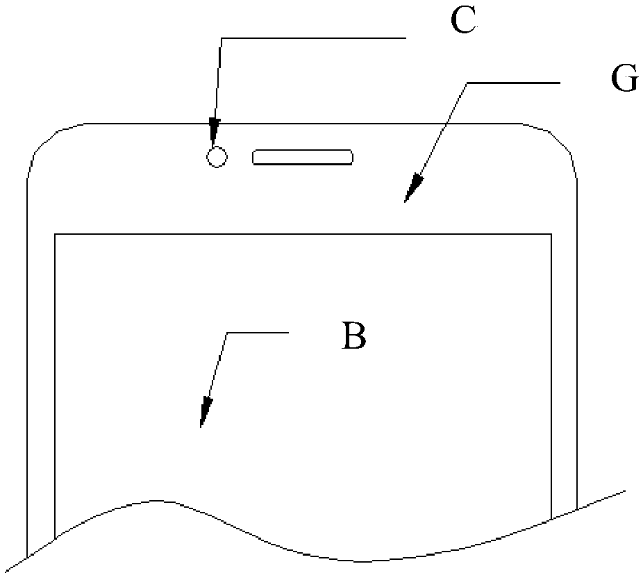
For example, refer to figure 2 , which shows the proportion of the appearance of an existing mobile phone. It can be seen that when the appearance hole C of the front camera is far away from the outer edge G of the LCM display area B, the area of ​​the non-LCM display area in the mobile phone panel in the Y direction is increased. size and corresponding area, resulting in a lower screen-to-body ratio
In addition, the position of the hole C on the appearance of the front camera leads to an uncoordinated proportion of the appearance of the mobile phone, thus affecting the visual effect of the mobile phone

Method used


Image

  • Camera and mobile terminal
  • Camera and mobile terminal
  • Camera and mobile terminal

Examples


Embodiment 1

[0049] refer to Figure 5 , which shows a schematic cross-sectional view of Embodiment 1 of a mobile terminal according to an embodiment of the present invention. The schematic cross-sectional view is specifically obtained along the vertical line in the Y-Y direction of the mobile terminal passing through the center of the circular cross-section of the front camera. The mobile terminal may specifically include: a fingerprint module 501, a main board cover 502, an LCM display area 503, a glass cover 504, an LCM 505, an FPC 506, a foam 507, and a front camera 508, wherein the LCM 505 is located between the front camera 508 and the fingerprint module. between the group 501; the LCM 505 and the glass cover 504 can be assembled into one component to realize the assembly with the main board upper cover 502; the main board upper cover 502 and the front camera 508 can be pressed together by the foam 507, The material between the front camera 508 and the FPC 506 can be removed so that ...

Embodiment 2

[0054] refer to Figure 9, which shows a schematic cross-sectional view of Embodiment 2 of a mobile terminal according to an embodiment of the present invention. The mobile terminal may specifically include: a main board upper cover 901, an FPC 902, a foam 903, and a front camera 904, wherein the main board upper cover 901 Between the front camera 904 and the front camera 904, the material between the front camera 904 and the FPC 902 can be pressed against the main board upper cover 901 through the foam 903, so it is necessary to ensure that the main board upper cover 901 and the FPC 902 and the main board upper cover 901 are not removed. Safe distance from the front camera 904.

[0055] Figure 9 , the cross-sectional outline 3 of the main board upper cover 901 and the cross-sectional outline 1 of the FPC 902 may have an offset relationship, so that the distance between the two can be reduced to a limit value; and, the cross-sectional outline of the main board upper cover 90...


PUM


Abstract

An embodiment of the present invention provides a camera and a mobile terminal, wherein the camera is applied to a mobile terminal, and may specifically include a lens, and the distance between the outline of the section of the lens and the outline of the section of adjacent components in the mobile terminal There is an offset relationship; wherein, the adjacent component is a component adjacent to the lens in the mobile terminal. The embodiment of the present invention can make the distance between the camera and the adjacent components reach the limit value while ensuring the safety clearance between the camera and the adjacent components.

Description

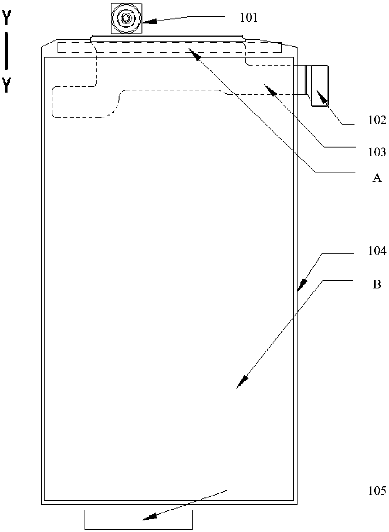
technical field [0001] The present invention relates to the technical field of mobile communication, in particular to a camera and a mobile terminal. Background technique [0002] At present, with the development of mobile communication technology, mobile terminals such as mobile phones have become necessities of people's lives. However, while the functions of the mobile phone are gradually enriched, it also brings many difficulties to the stacking design of the mobile phone. [0003] refer to figure 1 , shows a schematic diagram of a stack structure of an existing mobile phone, the mobile phone has a front fingerprint unlocking function and a front camera function, and the stack structure of the mobile phone in the vertical direction Y-Y may specifically include: a front camera 101, a BTB (board-to-board) , Board-to-Board) connector 102, FPC (flexible printed circuit board, Flexible Printed Circuitboard) 103, LCM (LCD display module, LCD Module) 104 and fingerprint module...

Claims


Application Information

Patent Timeline
Patent Type & Authority Patents(China)
IPC IPC(8): H04N5/225
CPCH04N23/57H04N23/55
Inventor 许经纬戢记球罗政军
Owner VIVO MOBILE COMM CO LTD
Learn More