Beam selection method and terminal equipment

A technology of terminal equipment and beams, applied in the field of communication, can solve the problems of high time overhead and many times of beam pairing at both ends of the transceiver.

Active Publication Date: 2016-11-23
HUAWEI TECH CO LTD
View PDF3 Cites 40 Cited by
  • Summary
  • Abstract
  • Description
  • Claims
  • Application Information

AI Technical Summary

Problems solved by technology

[0005] Embodiments of the present invention provide a beam selection method and a terminal device to solve the problem that when a terminal device with multi-level beams performs beam selection in the prior art, it is necessary to traverse all beams at both ends of the beam during the selection process of each level of beam. Pairing, resulting in more beam pairing times at the sending and receiving ends, and a larger time overhead

Method used


Image

  • Beam selection method and terminal equipment
  • Beam selection method and terminal equipment
  • Beam selection method and terminal equipment

Examples


Embodiment 1

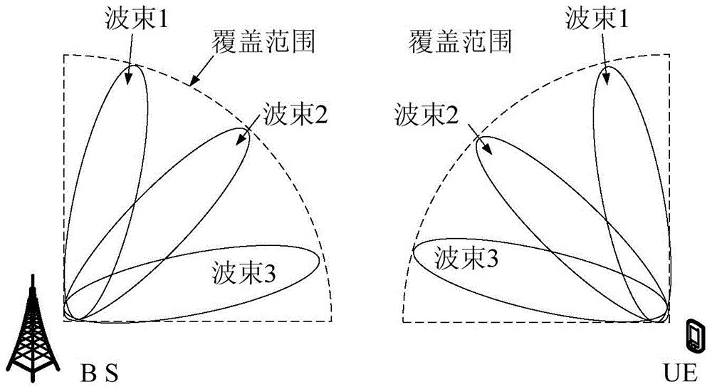
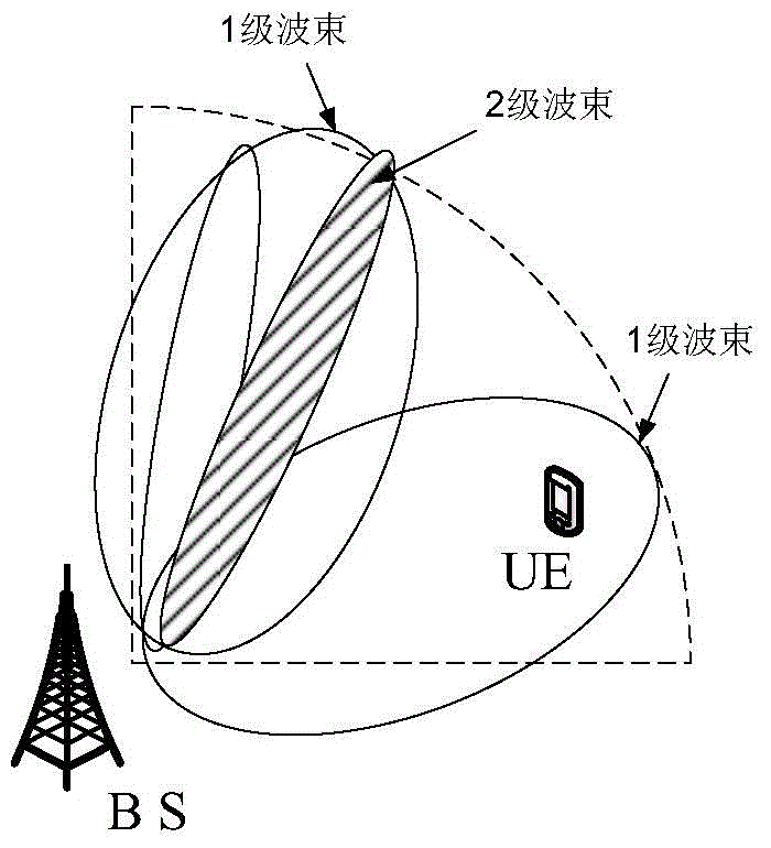
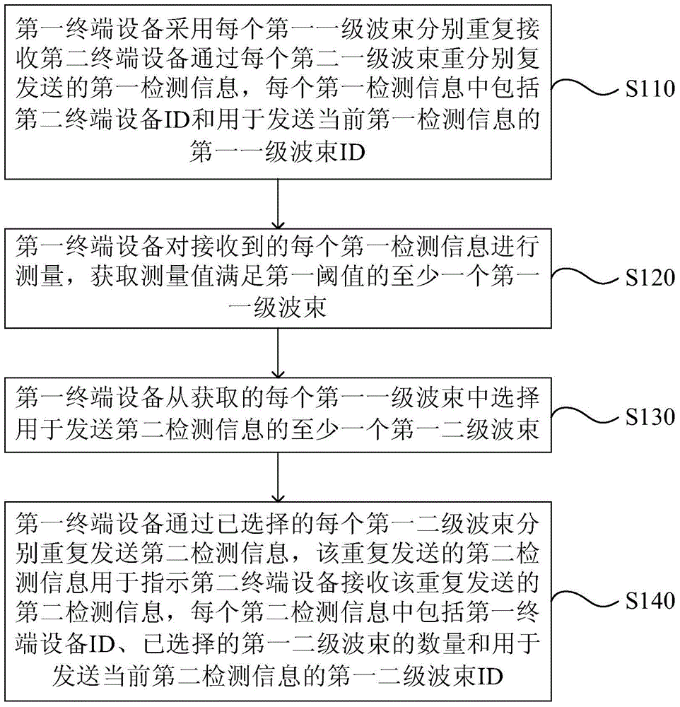
[0186] image 3 It is a flowchart of a beam selection method provided by Embodiment 1 of the present invention. The method provided in this embodiment is suitable for beam selection at both ends of the transceiver, where at least one end has multi-level beams. For example, the first terminal device performing the beam selection method has multiple first-level beams, and each first-level beam The first-level beams include a plurality of first-level beams, and the first terminal equipment is usually implemented by means of hardware and software, such as image 3 As shown, the method of this embodiment may include:

[0187] S110. The first terminal device uses each first-level beam to repeatedly receive the first detection information repeatedly sent by the second terminal device through each second-level beam, and each first detection information includes the second terminal A device identity (Identity, ID for short) and a first-level beam ID used to send the current first detec...

Embodiment 2

[0208] Figure 8 It is a flow chart of a beam selection method provided by Embodiment 2 of the present invention. in the above image 3 On the basis of the illustrated embodiment, in this embodiment, the opposite end that performs beam selection with the first terminal device, that is, the second terminal device also has multi-level beams, that is, each second-level beam includes multiple second-level beams. beam, the method of this embodiment specifically includes:

[0209] S210. The first terminal device uses each first-level beam to repeatedly receive the first detection information repeatedly sent by the second terminal device through each second-level beam, and each first detection information includes the second terminal device ID and the ID of the first level beam used to send the current first detection information.

[0210] In this implementation, the number of times the first terminal device receives the first detection information is also the number of the first ...

Embodiment 3

[0241] Figure 11 It is a flowchart of a beam selection method provided by Embodiment 3 of the present invention. The method provided in this embodiment is suitable for beam selection at both ends of the transceiver, where at least one end has multi-level beams, for example, the second terminal device performing the beam selection method has multiple second-level beams, and the first terminal at the opposite end The device has multiple first-level beams, and each first-level beam includes multiple first-level beams. The second terminal device in this embodiment is usually implemented by means of hardware and software, such as Figure 11 As shown, the method of this embodiment may include:

[0242] S310. The second terminal device uses each second-level beam to repeatedly send the first detection information to the first terminal device, wherein each first detection information includes the ID of the second terminal device and the information used to send the current first det...


PUM


Abstract

Embodiments of the invention provide a beam selection method and terminal equipment. The method comprises the following steps: first terminal equipment adopts each first primary beam to repeatedly receive first detection information repeatedly sent by each second primary beam; the first terminal equipment measures each piece of received first detection information, acquires at least one first primary beam of which the measured value meets a first threshold, and selects at least one first secondary beam used for sending second detection information from each acquired first primary beam; and the first terminal equipment repeatedly sends the second detection information through each selected first secondary beam. In the prior art, the terminal equipment with beams of multiple levels needs to traverse all pairings of beams at the sending and receiving ends in the selection process of beams of each level, which results in a large number of times of pairing of beams at the sending and receiving ends and heavy time overhead. By implementing the embodiments of the invention, the problem is solved.

Description

technical field [0001] Embodiments of the present invention relate to communication technologies, and in particular to a beam selection method and terminal equipment. Background technique [0002] Beamforming technology can form radio beams of specific shape and direction to improve signal quality to meet the increasing capacity requirements of wireless communication systems. Usually, the two ends of the data transmission and reception, such as the base station and the terminal equipment, have multiple beams, and the base station and the terminal equipment do not know the specific location of the other party. problem to be solved. [0003] The multi-level beams commonly used at present are multiple beams with independent orientation and width. According to the width of the beam, the multiple beams are divided into multiple levels, that is, multiple levels. The beam width of each level is gradually reduced. If required When the selection and pairing of the narrowest beams a...

Claims


Application Information

Patent Timeline
Patent Type & Authority Applications(China)
IPC IPC(8): H04W16/28
CPCH04W16/28
Inventor 孙杰叶枫
Owner HUAWEI TECH CO LTD
Why Eureka
Try Eureka