Method and device for receiving optical signals

An optical signal and optical receiver technology, applied in the field of network communication, can solve problems such as large time overhead and inability to achieve fast synchronization, and achieve the effect of reducing time overhead and fast synchronization

Inactive Publication Date: 2009-10-07
HUAWEI TECH CO LTD
View PDF0 Cites 25 Cited by
  • Summary
  • Abstract
  • Description
  • Claims
  • Application Information

AI Technical Summary

Problems solved by technology

[0006] The technical problem to be solved by the embodiments of the present invention is to provide a method and device for optical signal reception, which overcomes the shortcomings of the existing 10G / 1G EPON coexistence system that the multi-rate reception technology takes up a large time overhead and cannot achieve fast synchronization

Method used


Image

  • Method and device for receiving optical signals
  • Method and device for receiving optical signals
  • Method and device for receiving optical signals

Examples


Embodiment Construction

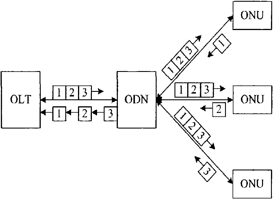
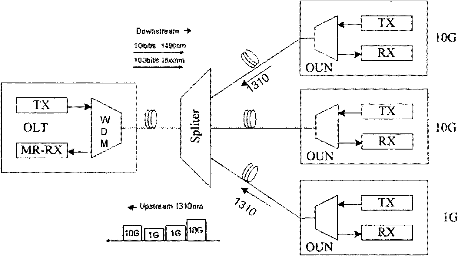
[0022] By adopting the embodiment of the present invention, it is possible to receive various optical signals with different transmission rates. For the convenience of description, only the optical signals at two rates of GEPON and 10G EPON are used as examples for illustration.

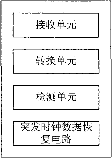
[0023] image 3 It is a schematic structural diagram of an optical receiver according to Embodiment 1 of the present invention. The optical receiver includes: a receiving unit, a conversion unit, a detection unit, and a burst clock data recovery circuit; wherein, the receiving unit is used to receive an optical signal, and the optical signal includes at least two optical signals with different transmission rates; the conversion unit, It is used to convert the received optical signal into a voltage signal; the detection unit is used to detect the transmission rate of the voltage signal, and output the control signal according to the detection result; the burst clock data recovery circuit is used to pe...


PUM


Abstract

The invention discloses an optical receiver which comprises a receiving unit, a converting unit, a detecting unit and a burst clock data recovering circuit, wherein the receiving unit is used for receiving optical signals which at least comprise optical signals having two different transmission rates; the converting unit is used for converting the received optical signals to voltage signals; the detecting unit is used for detecting the transmission rates of the voltage signals and outputting control signals according to the detecting result; and the burst clock data recovering circuit is usedfor recovering the clock and the data for the voltage signals according to the control signals. Correspondingly, the invention also discloses a method for receiving optical signals. By the invention,not only time multiplexing signals with two rates of GEPON and 10G EPON can be received, but also fast synchronization and time saving can be realized.

Description

technical field [0001] The invention relates to the field of network communication, in particular to a method and device for receiving an optical signal. Background technique [0002] Passive Optical Network PON is a point-to-multipoint optical fiber transmission and access technology, its structure is as follows figure 1 shown. It consists of the optical line terminal OLT at the office side, the optical network unit ONU or optical network terminal ONT at the user side, and the optical distribution network ODN. Among them, the transmission direction from OLT to ONU is the downlink direction, using TDM method, OLT continuously broadcasts information to each ONU, and each ONU chooses its own data to receive; the transmission direction from ONU to OLT is uplink direction, using TDMA method , that is, the uplink data transmission is bursty, different ONUs occupy different uplink time slots, and multiple ONUs share the uplink through time division multiplexing. [0003] In ord...

Claims


Application Information

Patent Timeline
Patent Type & Authority Applications(China)
IPC IPC(8): H04J3/06H04Q11/00
Inventor 冯志山杨涛
Owner HUAWEI TECH CO LTD
Why Eureka
Try Eureka