Methods and devices for spinal correction

A spine and intervertebral disc technology, applied in the direction of spinal implants, applications, analysis using fluorescence emission, etc., can solve the problem of indeterminate nerve monitoring

Active Publication Date: 2016-11-23
DEPUY SYNTHES PROD INC
View PDF9 Cites 4 Cited by
  • Summary
  • Abstract
  • Description
  • Claims
  • Application Information

AI Technical Summary

Problems solved by technology

However, neuromonitoring will not determine whether the process has built enough "space" (called nerve release) to relieve compression on the nerve

Method used


Image

  • Methods and devices for spinal correction
  • Methods and devices for spinal correction
  • Methods and devices for spinal correction

Examples


Embodiment Construction

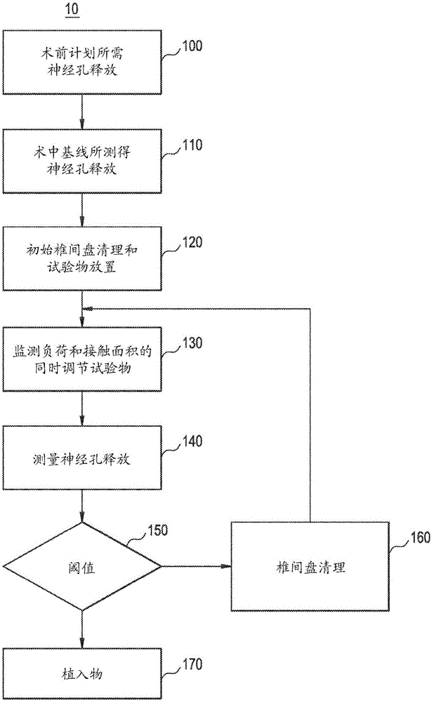
[0021] Figure 1a is a flowchart of an exemplary embodiment of a method 10 for performing spinal correction using an expandable trial implant and comprising monitoring the amount of nerve clearance achieved. While individual method steps are shown, not every step has to be performed, eg in some cases an intraoperative baseline may not be determined. Other steps can also be omitted.

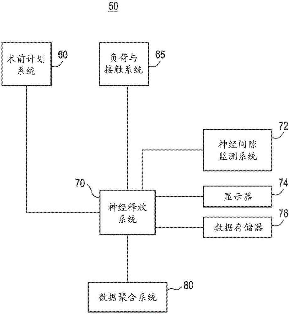
[0022] The spinal orthopedic method 10 can be implemented with the spinal orthopedic system 50 shown in FIG. 1b. As shown in FIG. 1 b , spinal orthopedic system 50 includes nerve release system 70 . Nerve release system 70 includes a nerve gap monitoring system 72 that determines information indicative of the amount of nerve gap achieved. The neural gap monitoring system 72 may be implemented in various embodiments, such as those that will be discussed in connection with FIGS. 2a-2f. The nerve release system 70 also includes a display device 74 and a data storage device 76 . The nerve release s...


PUM


Abstract

An expandable trial can include an inferior portion, a superior portion, and a middle expanding portion as well as load cells for monitoring the load on the trial. The trial may also include recesses on its lateral sides to provide spacing to accommodate a disc removal tool so tissue can be cleared monitoring load. In addition, neural foramen spacing can be monitoring to provide information about how much neural release has been achieved as the disc is cleaned and the spine is positioned and repositioned.

Description

technical field [0001] The present disclosure relates to spinal orthopedic methods and spinal orthopedic systems including expandable trial implants, and techniques for monitoring the amount of nerve clearance achieved and optionally the amount of intervertebral disc space distraction and forces on vertebral endplates. Background technique [0002] The human spine is a series of bony vertebrae separated by flexible disks called "discs." The intervertebral disc contains a compressible, flexible jelly-like center called the nucleus pulposus. This flexibility allows the spine to bend and twist. The annulus is a tougher fibrous material that surrounds and contains the nucleus pulposus, which might otherwise be squeezed out into other parts of the body. [0003] The human skeleton provides the architectural structure of the human body. The human spine not only provides the mechanical structure for supporting the body's weight, but it also provides passage for the "meridians" o...

Claims


Application Information

Patent Timeline
Patent Type & Authority Applications(China)
IPC IPC(8): A61F2/44
CPCA61F2/44A61F2/4657A61B17/1671A61F2/4611A61F2002/30405A61F2002/30471A61F2002/30507A61F2002/30515A61F2002/30556A61F2002/4633A61F2002/4658A61F2002/4666A61B5/6853A61B1/00087A61B1/3135A61B8/0858A61B8/0875A61B8/12A61B5/0071A61B5/055A61B5/1076A61B5/4566A61B2505/05A61B2562/04A61B2034/2055A61F2/4455A61F2002/30537A61F2002/30538A61F2002/30579A61B2090/064A61B2090/066A61B2090/065A61F2/4684A61B17/025A61B2017/0256A61B2017/00022A61B2017/00106A61B90/06A61F2/442
Inventor M.J.奥内尔R.罗姆利J.R.豪金斯C.拉姆齐Z.布特瓦拉J.迪皮特罗J.格里芬
Owner DEPUY SYNTHES PROD INC
Why Eureka
Try Eureka