Vehicular driving apparatus
A driving device, vehicle technology, applied in the direction of transmission, power device, fluid transmission, etc., can solve the problem of reducing the cooling efficiency of the rotating electrical machine MG, etc.
- Summary
- Abstract
- Description
- Claims
- Application Information
AI Technical Summary
Problems solved by technology
Method used
Image
Examples
Embodiment Construction
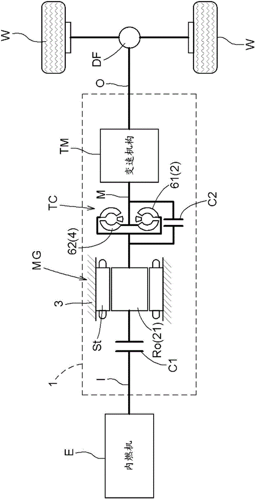
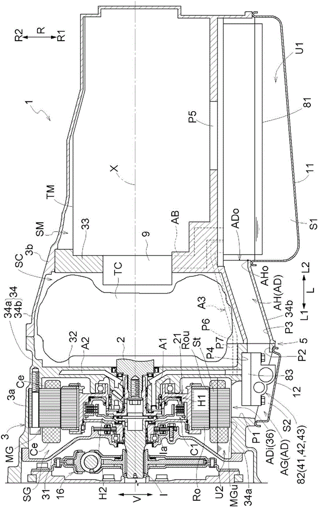
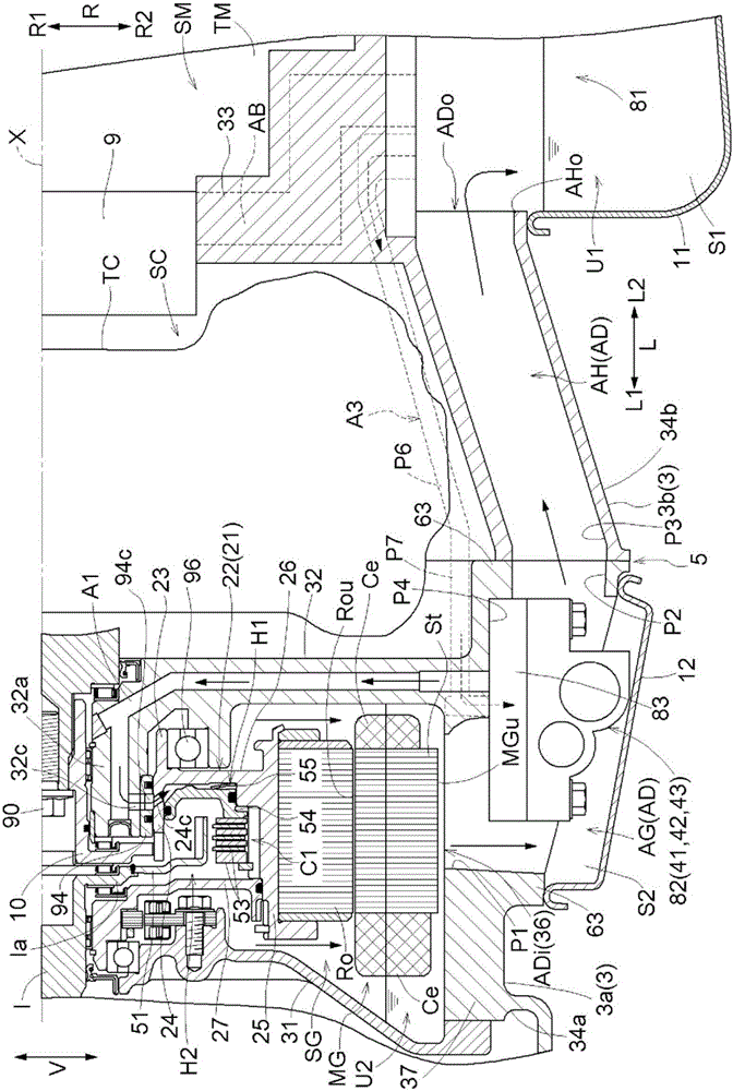
[0016] Embodiments of a vehicle drive device will be described with reference to the drawings. In addition, in the following description, unless otherwise specified, "axial direction L", "radial direction R", and "circumferential direction" refer to the input shaft of the speed change mechanism TM (the speed change input shaft, in this example is the axis center of the intermediate axis M) ( figure 2 The indicated axis X) is defined as the datum. In the present embodiment, all the rotating electric machine MG, the first clutch C1, and the torque converter TC are arranged coaxially with the transmission mechanism TM, so the respective "axial directions" of the rotating electric machine MG, the first clutch C1, and the torque converter TC , "radial direction" and "circumferential direction" correspond to "axial direction L", "radial direction R" and "circumferential direction" of the speed change mechanism TM, respectively. Also, the "first side L1 in the axial direction" mean...
PUM
 Abstract
Description
Claims
Application Information
 - R&D
- Intellectual Property
- Life Sciences
- Materials
- Tech Scout
- Unparalleled Data Quality
- Higher Quality Content
- 60% Fewer Hallucinations
Browse by: Latest US Patents, China's latest patents, Technical Efficacy Thesaurus, Application Domain, Technology Topic, Popular Technical Reports.
© 2025 PatSnap. All rights reserved.Legal|Privacy policy|Modern Slavery Act Transparency Statement|Sitemap|About US| Contact US: help@patsnap.com


