Bidirectional bearing, drive train, planetary gear and wind generator

A planetary gear and bearing technology, applied in the field of wind power generators, to achieve the effect of compact design

Inactive Publication Date: 2016-11-23
AREVA WIND
View PDF4 Cites 8 Cited by
  • Summary
  • Abstract
  • Description
  • Claims
  • Application Information

AI Technical Summary

Problems solved by technology

However, specifically in planetary gears there may be limited construction space for bearings

Method used


Image

  • Bidirectional bearing, drive train, planetary gear and wind generator
  • Bidirectional bearing, drive train, planetary gear and wind generator
  • Bidirectional bearing, drive train, planetary gear and wind generator

Examples


Embodiment Construction

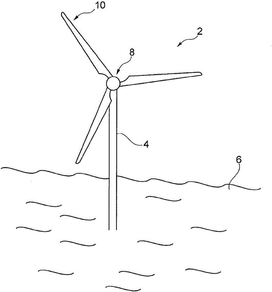
[0024] figure 1 is a simplified wind generator 2 according to an embodiment of the invention. The wind turbine 2 comprises a support structure 4 resting on a suitable foundation in the sea 6 . Merely by way of example, the wind generator 2 is an offshore wind generator. A nacelle (not visible) is arranged at the top of a support structure 4 which may be eg a tower. A rotor hub 8 carrying a plurality of rotor blades 10 is coupled to a main shaft 72 of a drive train 70 .

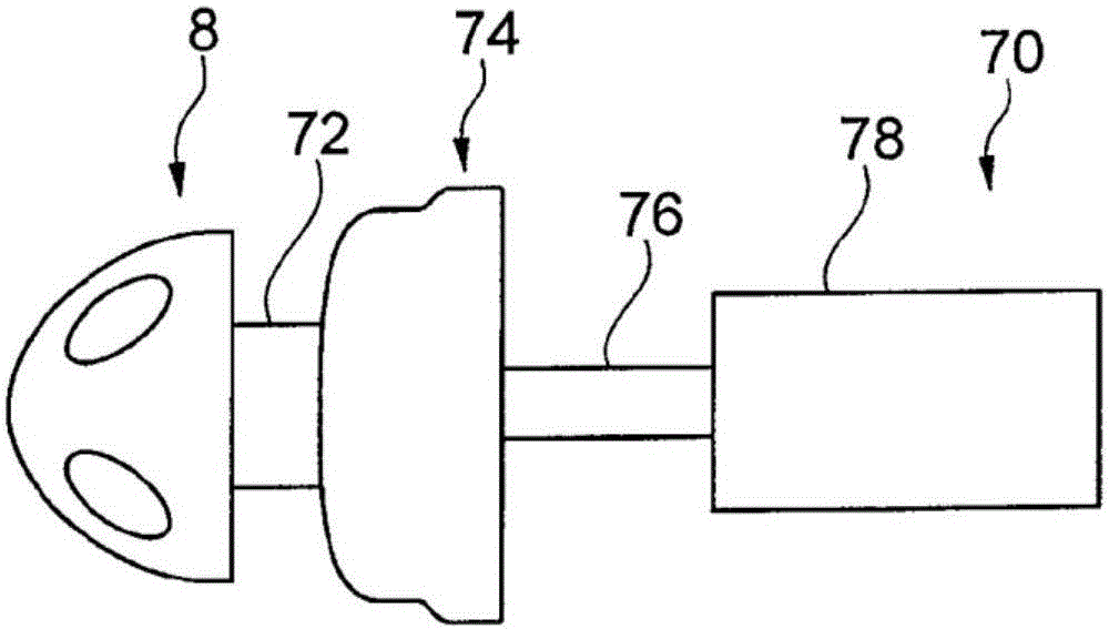
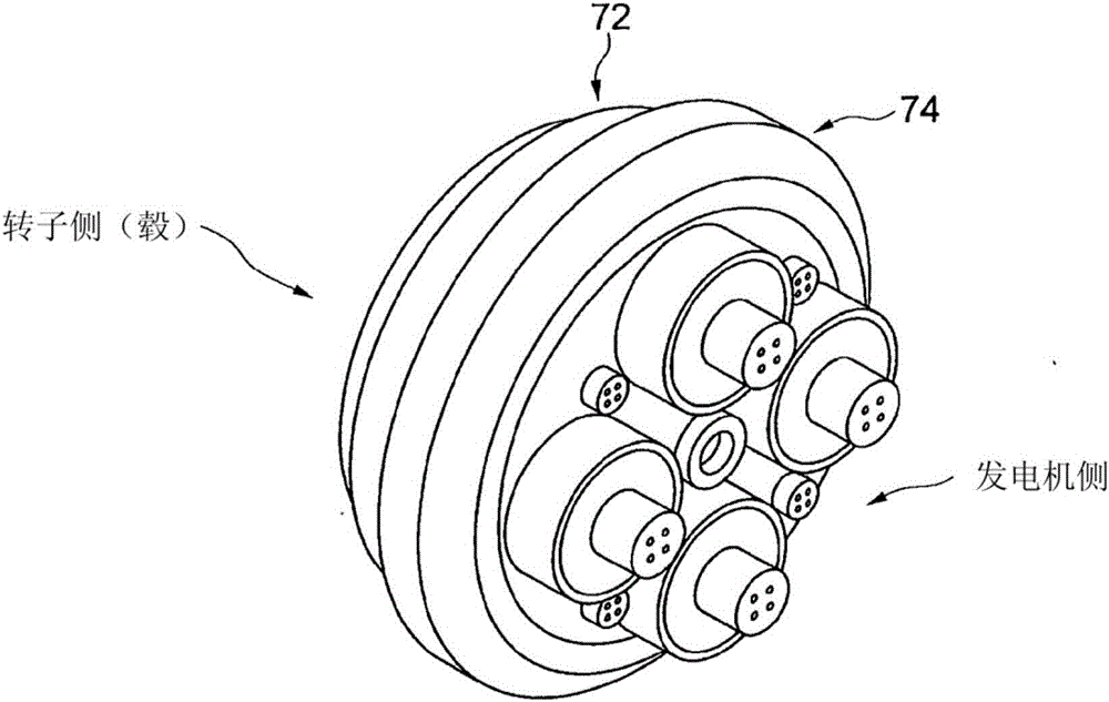
[0025] figure 2 A simplified drive train 70 is shown according to an embodiment of the invention. The drive train 70 may be arranged in the nacelle of the wind turbine 2 . The rotor hub 8 is coupled to a main shaft 72 which is the drive shaft for planetary gears 74 . The driven shaft of planetary gear 74 drives an input shaft 76 of generator 78 . Drive train 70 may include rotor hub 8 , main shaft 72 , planetary gears 74 and its output shaft, which is an input shaft 76 of generator 78 .

[0026] ima...


PUM


Abstract

A bidirectional bearing (30), a drive train, a planetary gear and a wind generator having a bidirectional bearing are provided. The bidirectional bearing comprises a outer bearing shell (32) having a first intermediate bearing shell (34), which is coupled to the shaft (40) and which cooperates with the outer bearing shell. The bidirectional bearing further comprises a second intermediate bearing shell (36), which is arranged opposite to the outer bearing shell with respect to the first intermediate bearing shell. The second intermediate bearing shell is configured to take up a first load having a first direction (D1) from the first intermediate bearing shell. Furthermore, the first second intermediate bearing shell is configured to receive a second load having a second direction (D2), which is substantially opposite to the first direction. The first intermediate bearing shell receives said second load from the second intermediate bearing shell and is configured to transfer this second load to the outer bearing shell.

Description

technical field [0001] The invention relates to a bidirectional bearing, a drive train, a planetary gear comprising a bidirectional bearing and a wind power generator with a planetary gear. Background technique [0002] Spherical bearings (also known as cup bearings) provide the gimbal or gimbal of a rotating part such as the shaft of a gear. The motion of the axis is constrained to a rotation. To mount the shaft in the axial direction, the spherical bearing acts as a double direction thrust bearing, allowing angular deflection between the shaft and the shaft support. For this purpose, the ball seat of the spherical bearing may be large enough to surround the spherical head of the bearing. According to an alternative design, the spherical bearing may include two reaction ball seats that limit the motion of the ball head to rotational motion. A third known design principle employs two separate spherical bearings forming a set of bearings that limit the movement of the ball...

Claims


Application Information

Patent Timeline
Patent Type & Authority Applications(China)
IPC IPC(8): F16C23/04F16H57/023F16H57/021F03D15/00
CPCF16C23/043F16C23/048F16H57/021F16H57/023F16C2360/31Y02E10/72F03D80/70
Inventor 克劳斯·皮舍尔
Owner AREVA WIND
Why Eureka
Try Eureka